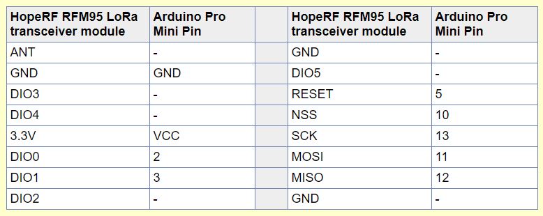
Pin Map I used:
Table
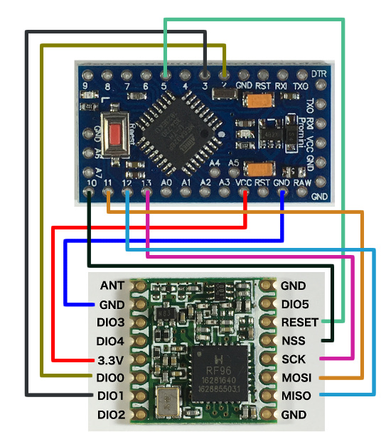
Schematic
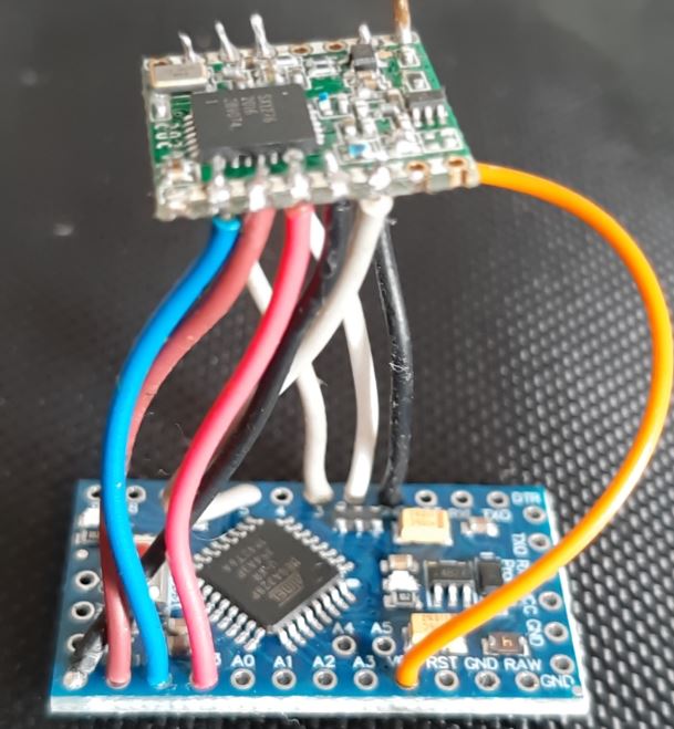
My board
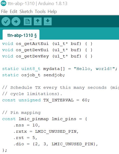
Sketch pinmap
I know it’s better to use a breadboard, but I don’t have one, so I use my soldering iron.
I checked connections, there is no bad contact or short.
I had an idea to simulate not working rfm module. I unsoldered VCC wire, RFM95 was not powered. In the console I saw:
Starting
FAILURE
C:\Users\lorauser\Documents\Arduino\libraries\arduino-lmic-matthijskooijman\src\lmic\radio.c:545
The message changed. RFM module is working. I soldered the VCC back. I’m back to initial message
Starting
Packet queued
132006: EV_TXCOMPLETE (includes waiting for RX windows)