Thanks for adding to the confusion for an already confused situation.
I’m old but not yet senile, so no, I hadn’t forgotten.
Bitrot has not yet set in and the deprecate button does not cause electrons around the world to suddenly stop the software working. I know, my devices are still happily sending …
Perhaps it would be worth reviewing the author’s deprecation message, where he explains that he wasn’t able to keep up with the bugfixes that were being made in the maintained ones.
So no, it’s not about bitrot, it’s about bits that were never right to begin with.
It may work after a fashion, but you’re locking yourself into a backwater that is unmaintained.
Sketch uses 20402 bytes (66%) of program storage space. Maximum is 30720 bytes.
Global variables use 901 bytes (43%) of dynamic memory, leaving 1147 bytes for local variables. Maximum is 2048 bytes.
Most of those exist in the deprecated project too, along with the many shared ones that the maintained branch has fixed. They’re just not being tracked over there.
Basically, the MCCI effort is exposing how deep the fundamental issues in all LMiC’s really run.
(That said, no small number of those issues have to do with the effort towards achieving actual LoRaWAN certification, which may be beyond the needs of most.
And another set are really user and platform problems more than LMiC ones, but get created because it’s code people are actively trying to integrate)
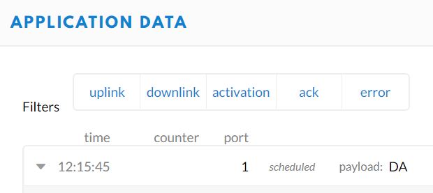
Does “ABP working” include downlinks such as the MAC commands for channel configuration and ADR?
Historically speaking, if the TTN console is showing join accepts being generated, then most alleged “ABP but not OTAA” have tracked back to being failures to receive downlinks, and many of those turn out to be timing issues, or bandplan misconfiguration ones.
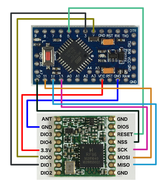
A possible cause of timing issues is not detecting the end of the uplink transmission, eg, with the appropriate DIO, which gets back to the pinmap… only I’d expect some sort of error or lockup if it was never seen, unless perhaps it was falsely seen the instant the code started looking for it.
My stock debug approach to all of that is to blip a GPIO when starting and ending both transmit and receive, and look at the time in between with a scope…
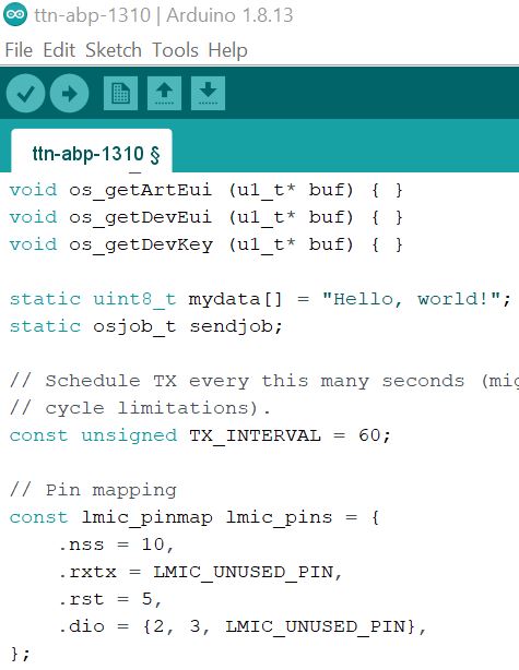
Tell me more about that. I’m using the simplest ttn-abp sketch example. Should I add this in my example? Taken from tutorial
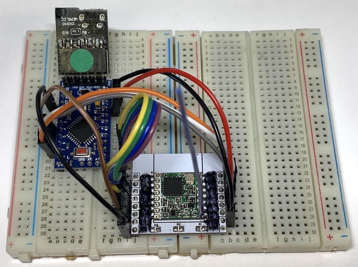
// Use with Arduino Pro Mini ATmega328P 3.3V 8 MHz
// Let LMIC compensate for +/- 1% clock error
LMIC_setClockError(MAX_CLOCK_ERROR * 1 / 100);
On which GPIO should I measure signals to see timings? I can measure only transmit (sending hello world), I’m not receiving anything.
The clock error thing has been poorly understand by many for a long time, and often causes as many problems as it solves. In some cases it may be useful, but needs to be used with a much more detailed understanding of specifics than the usual blindly hopeful “try this…” and may also require adjustment to the duration of the receive window in symbols.
To use a GPIO for checking timing, you’d need a storage scope (or USB logic analyzer) and pick an unused digital pin. Given LMiC is C code, you’d either need to figure out the actual AVR port pin involved and set/clear it by direct access to the appropriate PORTx register, or perhaps better create an extern "C" function in your Arduino code which the LMiC code could call to blip or toggle it. Then you need to find the code that detects the end of transmission, and the code that starts reception, and put the manipulation of the test GPIO there.
Capturing all of the SPI traffic and relevant end-of-transmit DIO with a USB logic analyzer could be another approach, not requiring software changes to support.
(If this sounds complicated and not what one bargained for in choosing an Arduino approach, that’s because it is. If one is going to use LMiC, especially under Arduino, then it really makes sense to chose a board supported by and used for regression tests of a maintained LMiC. Otherwise you’re basically in the complexity territory of a professional embedded development project, with the added complication of a project/library interaction which makes things even harder to work on than usual…)
It’s unclear if you mean the SPI clock or the analyzer sampling rate. What sampling rate did you use? 1/8 of a uS would suggest you might be looking at the period of 8 MHz sampling, if the SPI clock is really that fast you’d need to run the analyzer faster.
Anyway, what you’d really want to be seeing is a sequence such as:
Chip select framed SPI operations to configure radio for transmission
tens to hundreds of milliseconds of nothing (matching calculated packet duration)
DIO change indicating end of transmission
just under 5000 uS of delay for 5 second RX1
Chip select framed sequence of SPI operations to set up receive
the above completing just before 5000 uS has elapsed from the end of transmit
DIO indicating reception… or else failure
One thing you need to make sure is that there’s some electrical activity to mark when the attempt at receiving ends in the case of getting nothing. I forget exactly how LMiC does this - maybe a DIO, maybe polling?
One of the historic issues with the clock error stuff for example is that it sometimes causes the receive attempt to begin early enough, that it then actually gives up before the preamble of the packet is actually due.