Yes LMIC uses its pins. In the README of the LMIC folder here is what is filled in
" The LMIC library needs only access to DIO0, DIO1 and DIO2, the other DIOx pins can be left disconnected.
In LoRa mode the DIO pins are used as follows:
DIO0: TxDone and RxDone
DIO1: RxTimeout ".
And on the card I haden’t connected these pins using jumpers.
I will test and get back to you on the result obtained by implementing all its prerequisites.
I saw the README.
I installed the version v4.1.1.
And here is what is said following the Pin Mapping :
“The names refer to the pins on the transceiver side, the numbers refer
to the Arduino pin numbers (to use the analog pins, use constants like A0). For the DIO pins, the three numbers refer to DIO0, DIO1 and DIO2
respectively. Any pins that are not needed should be specified as LMIC_UNUSED_PIN. The NSS and dio0 pins are required. The others can
potentially left out (depending on the environments and requirements,
see the notes above for when a pin can or cannot be left out).”
And also on the card I didn’t connecte these pins using jumpers.
I will test and get back to you on the result obtained by implementing all its prerequisites.
There’s no point duplicating the information in replies, we can all see them.
Hmmmm, I wonder how you ended up with the older (deprecated) repro’s radio.c which you quoted above as it is the only one that has the assert on line 689.
As this thread is getting rather protracted, the short version of your problem is that the code is requesting the version of the radio chip and not getting back the result it expects. This means one or more of:
The shield is not plugged in quite right for the Mega - check that the pin numbers on the shield align with the pins on the Mega.
The shield has an issue of some sort, ie it’s broken.
The Arduino has an issue of some sort, it it’s broken
The thing to try after checking the pin matching when you plug it in if that doesn’t make it work is to scroll up this thread to the very top and use @LoRaTracker’s library to run some diagnostics.
It that’s not able to talk to the radio I’d unplug the shield, try another SPI device to test that on the Mega and if that works, use jumper cables to link the shield to the Arduino. If another SPI device won’t work, then I’d suspect the Mega or the other device. So having another Mega would be useful. Or an Uno, which won’t have the space to run the LMIC but you can at least run the diagnostic library.
A user called phairou did raise the same issue a few days ago over in the Arduino forums, same pictures etc. Although the documention requested on the shield pinouts was apprently not available at the time.
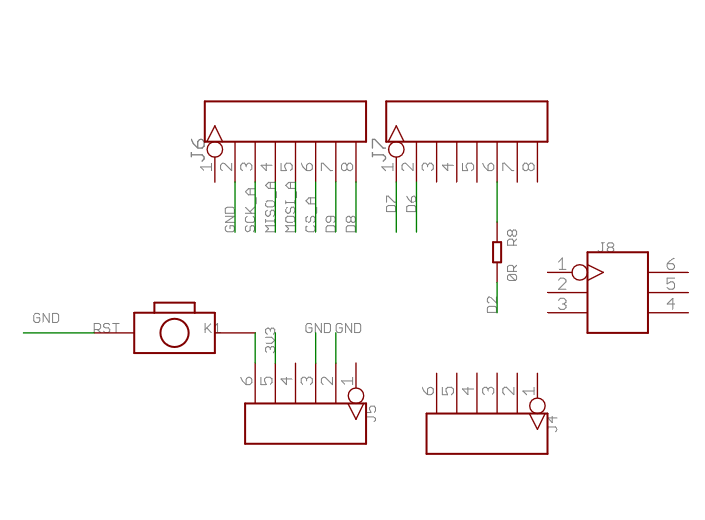
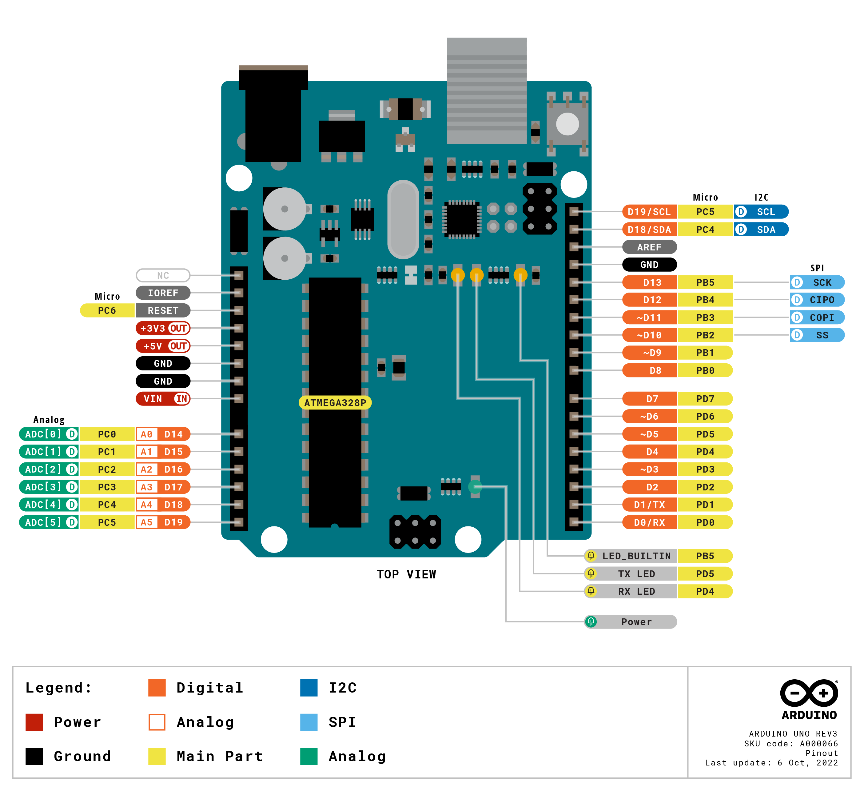
The documentation linked in this series of posts suggests the shield uses pins 13,12,11 for SPI, which wont work on a Mega 2560.
J8 appears to be the SPI\ISP connector which is what the shield should really be using to pickup the appropriate SPI connections.
Sorry, that’s when I had the old version of LMIC. Now it no longer puts \LMIC-Arduino\src\lmic\radio.c:689 but rather \MCCI_LoRaWAN_LMIC_library\src\lmic\oslmic.c:53.
I have done the Pin mapping below following the board branch shown here https://www.makerfabs.com/desfile/files/LoRa%20%20Radio%20Shield%20user’s%20manual.pdf:
const lmic_pinmap lmic_pins = {
.nss=10,
.rxtx = LMIC_UNUSED_PIN,
.rst=9,
.dio = {, 6, 7},
}
But I still have the same error. All weekend I was on this and still not resolved.
Ok @LoRaTracker I noted except that I currently have 5 arduino mega cards and it’s part of a project so I have to use the Mega cards. And the dragino LoRa shields are no longer available in stock, which is why I chose LoRa shields.
And what can you infer from that section of the code?
I’ve just looked at a couple of my Mega’s and I’m unclear why the shield fitted at the USB end with the pins aligned wouldn’t make the correct connections.
A future quote for your report: “I had to use Arduino Mega boards which won’t connect to a LoRa shield so the project totally failed”. You may want to revise your use of the word “have”.
From what I understand it’s a pin initialization issue.
Is the pin mapping i posted earlier good then?
And also by just launching the compilation of the code I also have this:
“#pragma message(“Board not supported – use an explicit pinmap”)”
On an Arduino DUE the SPI pins are (only) on the same connector as they are on a UNO and Mega, the central SPI\ICSP connector.
So if shield designers want to build hardware compatible shields they can, but they seem to choose not to.
This issue was raised over in the Arduino forum some days back and the OP was asked to check if the SPI pins on the LoRa module were connected to the central SPI\ICSP connector …