Arduino Pro Mini RFM95 pinmap problem

Hi all,

I’m trying to build a LoRa node based on the Arduino Pro Mini (ATmega328P 3.3V), an RMF95, and the MCCI LoRaWAN LMIC Library. Basically, I’m following this tutorial.

I haven’t gotten it to work however, and I think it’s because the Arduino is not communicating with the RMF95. I’m trying to run the ttn-otaa.ino example included in the library. During compiling it throws the following warning:

…\Arduino\libraries\MCCI_LoRaWAN_LMIC_library\src\hal\getpinmap_thisboard.cpp: In function ‘const Arduino_LMIC::HalPinmap_t* Arduino_LMIC::GetPinmap_ThisBoard()’:
…\Arduino\libraries\MCCI_LoRaWAN_LMIC_library\src\hal\getpinmap_thisboard.cpp:65:72: note: #pragma message: Board not supported – use an explicit pinmap
#pragma message(“Board not supported – use an explicit pinmap”)

I do have the correct pinmap set in the ttn-otaa.ino script (as per the tutorial I listed earlier). It does compile however, and when it runs on the board it spits out the following message on the serial line:

Starting
FAILURE
…\Arduino\libraries\MCCI_LoRaWAN_LMIC_library\src\lmic\oslmic.c:53

I’ve traced this error back to the following section of code (radio.c line 1091):

// some sanity checks, e.g., read version number
u1_t v = readReg(RegVersion);
#ifdef CFG_sx1276_radio
if(v != 0x12 )
return 0;

The readReg function tries to read the version number from the RFM95 module, but it doesn’t return anything. When I check the SPI line with a logic analyzer it is completely quiet as well, so everything seems to point to some HAL error (probably the pinmap).

Can anyone point me in the right direction? I’ve been stuck on this for days!

There is an Arduino program here which needs no library installed that (on a Pro Mini) you only need to connect the SPI pins correctly SCK, MOSI, MISO and NSS, you can leave NRESET and DIOx pins not connected. The program checks that the device registers can be read and written to and tells you the version number;

Works on all SX127X devices and there is a similar one for SX126X and SX128X devices.

2 Likes

Thank you very much LoRaTracker. I figured it out using your program!

At first the program reported “No device found”, but after I tied the RESET pin on of the RFM95 to high (3.3V), it started responding. I guess it was in a perpetual state of resetting or something. The thick layer of flux around the pins due to my shitty soldering probably didn’t help much either, so I cleaned that up too.

Thank you for your help :innocent:

1 Like

There should have been no need to pull the pin high, just leave in not-connected, as suggested in the instructions “Leave the NRESET and DIOx pins not connected”.

However, if after the cleanup, you still need to pull the pin externally high, then something is wrong as that pin has its own internal pull up…

1 Like

You’re right, it also works with the RESET pin unconnected.

Hi, I have the same problem as Catnip. I used this program to check registers and I get “no device responding” but I do get the module version (0x12). What can be the problem?

No supported Arduino maybe.

Faulty device.

Device not wired correctly or soldering issue as described by the original poster.

Did you also try the ‘MCCI LoRaWAN LMIC’ library ?

1 Like

I tried both with Arduino Uno and Nano Every and I get the sane error. I’ve tested MCCI LoRaWAN LMIC, too. Beside the oslmic.c:53 error in the serial monitor, I get a pinmap error in the compiler. Wiring is ok, so I guess I have to accept that it’s a soldering problem, due to my terrible soldering skills. I’ll post some pics of that.
image
image
image

Your Gnd joint looks like it could be a dry joint.

I’d touch each of them up looking to remove the excess solder and make sure it flows like a liquid. The soldering iron tip can not transfer any heat by itself, there must be a small amount of solder on it to do that for you. But not so much that you can start sculpting with it.

I think you’ll see it’s a warning about you having to define the pin map, not an error.

I’d stick with the Nano Every - far more room for both program and variables.

You don’t need to test MCCI LMIC, it definitely works (I was coding on it most of the weekend), you just have to tell it which pins are being used for NSS, DIO0 and DIO1. Once you’ve got that going, you can focus on the EUI’s & AppKey.

With the appropriate 5V to 3.3V Logic level conversion circuits I presume.

That device does not look like any of the Hope RFM95s I have seen. Hope normally have a different marking on the RF chip they use RF95.

I would alse be very cautious wiring LoRa modules up like that, if the antenna wire becomes disconnected when you attempt to transmit it could let the devices magic smoke out.

1 Like

Thank you. I’ll proceed with the soldering tips you gave me, trying to fix it. And then try again with LMIC. I’ll update you. (By the way, I’m using a “single channel” Raspberry Pi 4 Lora Gateway, I saw in the forum that it’s not a good idea)

Eeeehm, nope. I am not using a logic level converter… I saw video on youtube of people not using it… By the way, I also have a Hope LoRa module, but I think I’ve damaged it.
image
image

So not only, zapping 3.3V module with 5V and solder bridges but also …

We don’t say it’s not a good idea, we say they should not be used due to the disruption to the network. And you have to alter LMIC to be able to cope with a SPCF which isn’t trivial.

Please disconnect immediately and read: Single Channel Packet Forwarders (SCPF) are obsolete and not supported

If you want to make some progress, get a TTIG for a gateway and buy a board supported by LMIC-node. I’d normally recommend the Adafruit Feather M0 with RFM95 but in this instance, as it requires some delicate soldering, maybe best to pick something else. :wink:

Thanks for your rapid answer and kind suggestions! Do you think I still can make it with Arduino Nano Every, 3.3 to 5 V logic level converter and a Hope module?

I’ve a test device with a Nano Every and I have my own PCB with an ATmega4808 + RFM95 on it, it works fine with LMIC once you know LMIC.

You may want to use a breadboard & jumper cables until you’ve refined your soldering technique.

You still need a proper gateway.

I have the same problem with Dragino Lora Shield + Arduino Uno.
When I use your program, I get only this.
Capture

I am not told weather the lora device is found or not.
Any advice for me?

There are no writes to the LoRa device, something strange there.

Look at the code, It has to print found or not found;

if (begin(NSS))
  {
    Serial.println(F("LoRa Device found"));
  }
  else
  {
    Serial.println(F("No device responding"));
  }

Which TTN library have you tried ?

An additional comment: Some of the registers are not what the should be, so it looks like there are read problems over the SPI bus.

As per the program notes the startup should be:


2_Register_Test Starting
LoRa Device found
Device version 0x12
Frequency at Start 434000000
Registers at Start 
Reg    0  1  2  3  4  5  6  7  8  9  A  B  C  D  E  F
0x00  00 09 1A 0B 00 52 6C 80 00 4F 09 2B 20 08 02 0A 

etc.
1 Like

Thanks for the reply, I think I purchased a faulty dragino lora shield. Even the light on the shield was not turning one, once it was connected to power.
I think it was a faulty one.

Good morning,
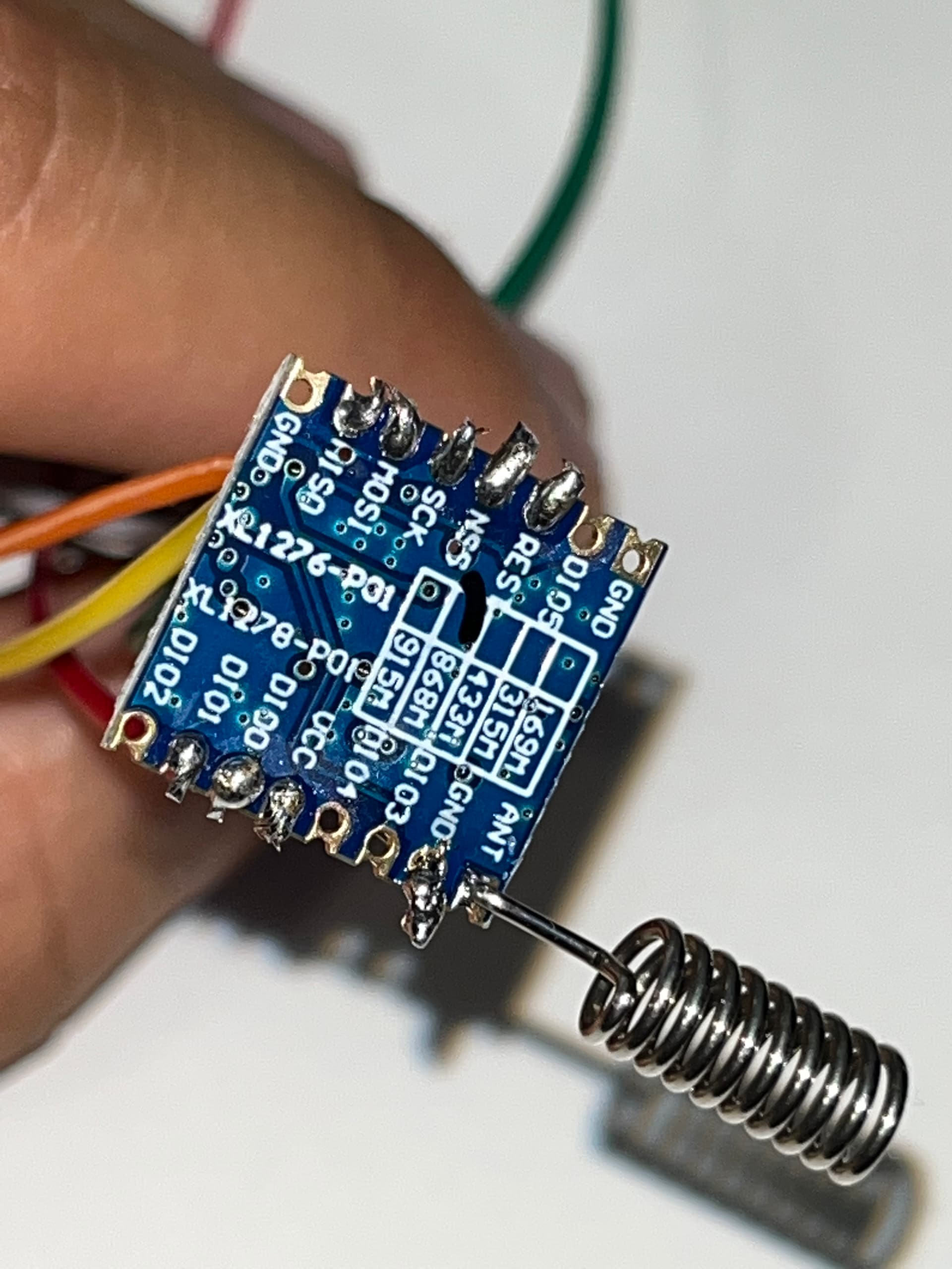
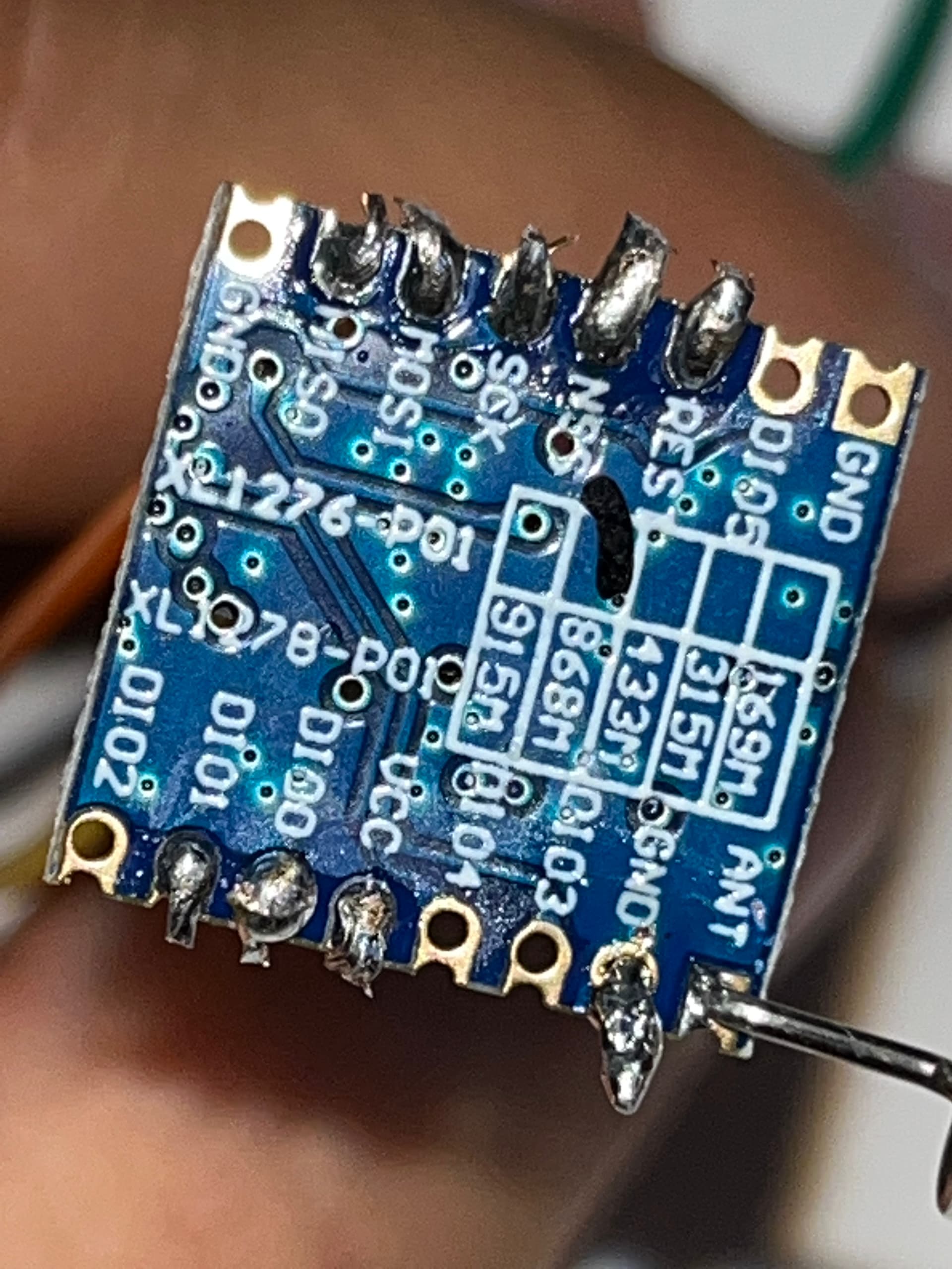
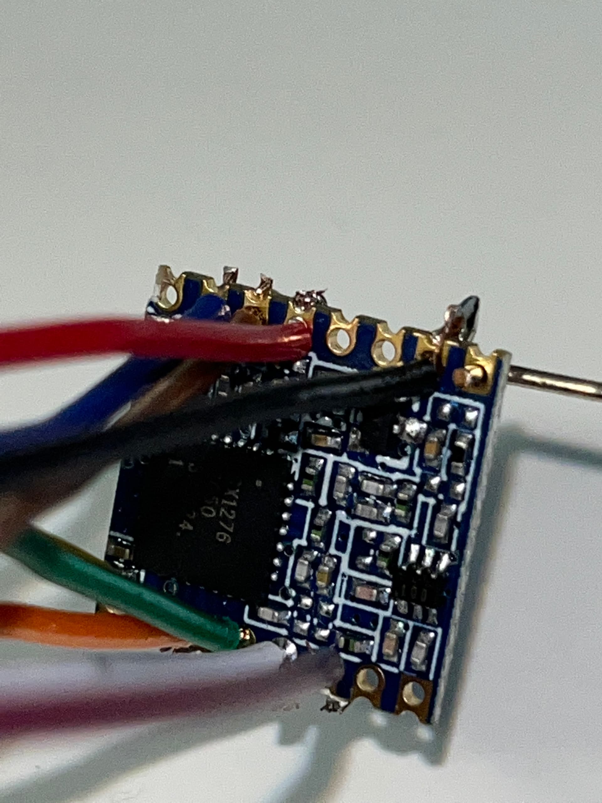
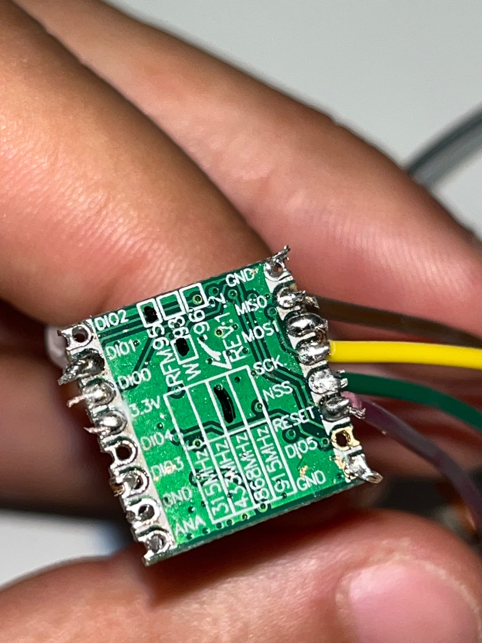
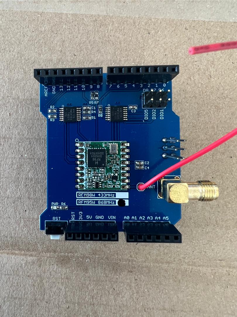
I am using an Arduino Mega 2560 board with a LoRa Shield RFM95W radio module. However I use LMIC to send my data to a Dragino LPS8N gateway.
And when I upload my program to the Arduino board nothing happens and I get the error displayed on the serial monitor:
Arduino\libraries\LMIC-Arduino\src\lmic\radio.c:689

Here is the picture of the shield :slight_smile:

Help me please.
Here is my test code on arduino:

const int Pintest =13;
//---------------------------------------------------

#include <lmic.h>
#include <hal/hal.h>
#include <SPI.h>

// LoRaWAN NwkSKey, network session key
// This is the default Semtech key, which is used by the early prototype TTN
// network.
static const PROGMEM u1_t NWKSKEY[16] = { 0x91, 0xA4, 0xAE, 0x05, 0x61, 0x89, 0x16, 0xCF, 0x09, 0x73, 0x51, 0x70, 0x19, 0xD1, 0xC3, 0xE2 };

// LoRaWAN AppSKey, application session key
// This is the default Semtech key, which is used by the early prototype TTN
// network.
static const u1_t PROGMEM APPSKEY[16] = { 0x79, 0xDB, 0xD8, 0xE4, 0x98, 0xF8, 0x19, 0xE1, 0xA6, 0x52, 0x5D, 0x4F, 0x79, 0x43, 0x71, 0x5D };

// LoRaWAN end-device address (DevAddr)
static const u4_t DEVADDR = 0x010C2D70; // ← Change this address for every node!

// These callbacks are only used in over-the-air activation, so they are
// left empty here (we cannot leave them out completely unless
// DISABLE_JOIN is set in config.h, otherwise the linker will complain).
void os_getArtEui (u1_t* buf) { }
void os_getDevEui (u1_t* buf) { }
void os_getDevKey (u1_t* buf) { }

static uint8_t mydata = “Hello, world!”;
static osjob_t sendjob;

// Schedule TX every this many seconds (might become longer due to duty
// cycle limitations).
const unsigned TX_INTERVAL = 10;

// Pin mapping
const lmic_pinmap lmic_pins = {
.nss = 10,
.rxtx = LMIC_UNUSED_PIN,
.rst = 9,
.dio = {2, 6, 7},
};

void onEvent (ev_t ev) {
Serial.print(os_getTime());
Serial.print(": ");
switch(ev) {
case EV_SCAN_TIMEOUT:
Serial.println(F(“EV_SCAN_TIMEOUT”));
break;
case EV_BEACON_FOUND:
Serial.println(F(“EV_BEACON_FOUND”));
break;
case EV_BEACON_MISSED:
Serial.println(F(“EV_BEACON_MISSED”));
break;
case EV_BEACON_TRACKED:
Serial.println(F(“EV_BEACON_TRACKED”));
break;
case EV_JOINING:
Serial.println(F(“EV_JOINING”));
break;
case EV_JOINED:
Serial.println(F(“EV_JOINED”));
break;
case EV_RFU1:
Serial.println(F(“EV_RFU1”));
break;
case EV_JOIN_FAILED:
Serial.println(F(“EV_JOIN_FAILED”));
break;
case EV_REJOIN_FAILED:
Serial.println(F(“EV_REJOIN_FAILED”));
break;
case EV_TXCOMPLETE:
Serial.println(F(“EV_TXCOMPLETE (includes waiting for RX windows)”));
if (LMIC.txrxFlags & TXRX_ACK)
Serial.println(F(“Received ack”));
if (LMIC.dataLen) {
Serial.println(F(“Received “));
Serial.println(LMIC.dataLen);
Serial.println(F(” bytes of payload”));
}
// Schedule next transmission
os_setTimedCallback(&sendjob, os_getTime()+sec2osticks(TX_INTERVAL), do_send);
break;
case EV_LOST_TSYNC:
Serial.println(F(“EV_LOST_TSYNC”));
break;
case EV_RESET:
Serial.println(F(“EV_RESET”));
break;
case EV_RXCOMPLETE:
// data received in ping slot
Serial.println(F(“EV_RXCOMPLETE”));
break;
case EV_LINK_DEAD:
Serial.println(F(“EV_LINK_DEAD”));
break;
case EV_LINK_ALIVE:
Serial.println(F(“EV_LINK_ALIVE”));
break;
default:
Serial.println(F(“Unknown event”));
break;
}
}

void do_send(osjob_t* j){
// Check if there is not a current TX/RX job running
if (LMIC.opmode & OP_TXRXPEND) {
Serial.println(F(“OP_TXRXPEND, not sending”));
} else {

     uint8_t buff[3];
    
     buff[0] = 1;
    LMIC_setTxData2(1, buff, sizeof(buff), 0);
    Serial.println(F("Packet queued"));
}
// Next TX is scheduled after TX_COMPLETE event.

}

void setup() {
Serial.begin(115200);
#ifdef VCC_ENABLE
// For Pinoccio Scout boards
pinMode(VCC_ENABLE, OUTPUT);
digitalWrite(VCC_ENABLE, HIGH);
delay(1000);
#endif
//----------------------------------------------------
pinMode(Pintest, OUTPUT);

// LMIC init
os_init();
// Reset the MAC state. Session and pending data transfers will be discarded.
LMIC_reset();
LMIC_setClockError(MAX_CLOCK_ERROR * 10 / 100);
// Set static session parameters. Instead of dynamically establishing a session
// by joining the network, precomputed session parameters are be provided.
#ifdef PROGMEM
// On AVR, these values are stored in flash and only copied to RAM
// once. Copy them to a temporary buffer here, LMIC_setSession will
// copy them into a buffer of its own again.
uint8_t appskey[sizeof(APPSKEY)];
uint8_t nwkskey[sizeof(NWKSKEY)];
memcpy_P(appskey, APPSKEY, sizeof(APPSKEY));
memcpy_P(nwkskey, NWKSKEY, sizeof(NWKSKEY));
LMIC_setSession (0x1, DEVADDR, nwkskey, appskey);
#else
// If not running an AVR with PROGMEM, just use the arrays directly
LMIC_setSession (0x1, DEVADDR, NWKSKEY, APPSKEY);
#endif

#if defined(CFG_eu868)
// Set up the channels used by the Things Network, which corresponds
// to the defaults of most gateways. Without this, only three base
// channels from the LoRaWAN specification are used, which certainly
// works, so it is good for debugging, but can overload those
// frequencies, so be sure to configure the full frequency range of
// your network here (unless your network autoconfigures them).
// Setting up channels should happen after LMIC_setSession, as that
// configures the minimal channel set.
// NA-US channels 0-71 are configured automatically
LMIC_setupChannel(0, 868100000, DR_RANGE_MAP(DR_SF12, DR_SF7),  BAND_CENTI);      // g-band
LMIC_setupChannel(1, 868300000, DR_RANGE_MAP(DR_SF12, DR_SF7B), BAND_CENTI);      // g-band
LMIC_setupChannel(2, 868500000, DR_RANGE_MAP(DR_SF12, DR_SF7),  BAND_CENTI);      // g-band
LMIC_setupChannel(3, 867100000, DR_RANGE_MAP(DR_SF12, DR_SF7),  BAND_CENTI);      // g-band
LMIC_setupChannel(4, 867300000, DR_RANGE_MAP(DR_SF12, DR_SF7),  BAND_CENTI);      // g-band
LMIC_setupChannel(5, 867500000, DR_RANGE_MAP(DR_SF12, DR_SF7),  BAND_CENTI);      // g-band
LMIC_setupChannel(6, 867700000, DR_RANGE_MAP(DR_SF12, DR_SF7),  BAND_CENTI);      // g-band
LMIC_setupChannel(7, 867900000, DR_RANGE_MAP(DR_SF12, DR_SF7),  BAND_CENTI);      // g-band
LMIC_setupChannel(8, 868800000, DR_RANGE_MAP(DR_FSK,  DR_FSK),  BAND_MILLI);      // g2-band
// TTN defines an additional channel at 869.525Mhz using SF9 for class B
// devices' ping slots. LMIC does not have an easy way to define set this
// frequency and support for class B is spotty and untested, so this
// frequency is not configured here.
#elif defined(CFG_us915)
// NA-US channels 0-71 are configured automatically
// but only one group of 8 should (a subband) should be active
// TTN recommends the second sub band, 1 in a zero based count.
// https://github.com/TheThingsNetwork/gateway-conf/blob/master/US-global_conf.json
LMIC_selectSubBand(1);
#endif

// Disable link check validation
LMIC_setLinkCheckMode(0);

// TTN uses SF9 for its RX2 window.
LMIC.dn2Dr = DR_SF9;

// Set data rate and transmit power for uplink (note: txpow seems to be ignored by the library)
LMIC_setDrTxpow(DR_SF7,14);

// Start job

do_send(&sendjob);

}

//----------------------------------------------------------------------
void loop() {
// put your main code here, to run repeatedly:
os_runloop_once();
digitalWrite(Pintest,HIGH);
delay(1000);
digitalWrite(Pintest,LOW);
delay(1000);

}
//------------------------------------------------------------------

What does it say on this line of the code?