I tried this one, thinking I could use it instead of the Arduino setup (since it says “Programmer Board”), but I needed to upload a bootloader to the ATTINY85 first.
I ended up using the Arduino setup to first load the bootloader (and then also the program since that was just as easy).
OK I thought to that you could use it to upload a bootloader 
Yeah, it is different for the ones with the ATtiny85 integrated into the board:
Those already have the bootloader installed and can be used straight away by just plugging them into USB (and install all the needed stuff in the Arduino IDE of course)>
In price they only add 20 cents to the chip, but they expect 5V instead of 3V.

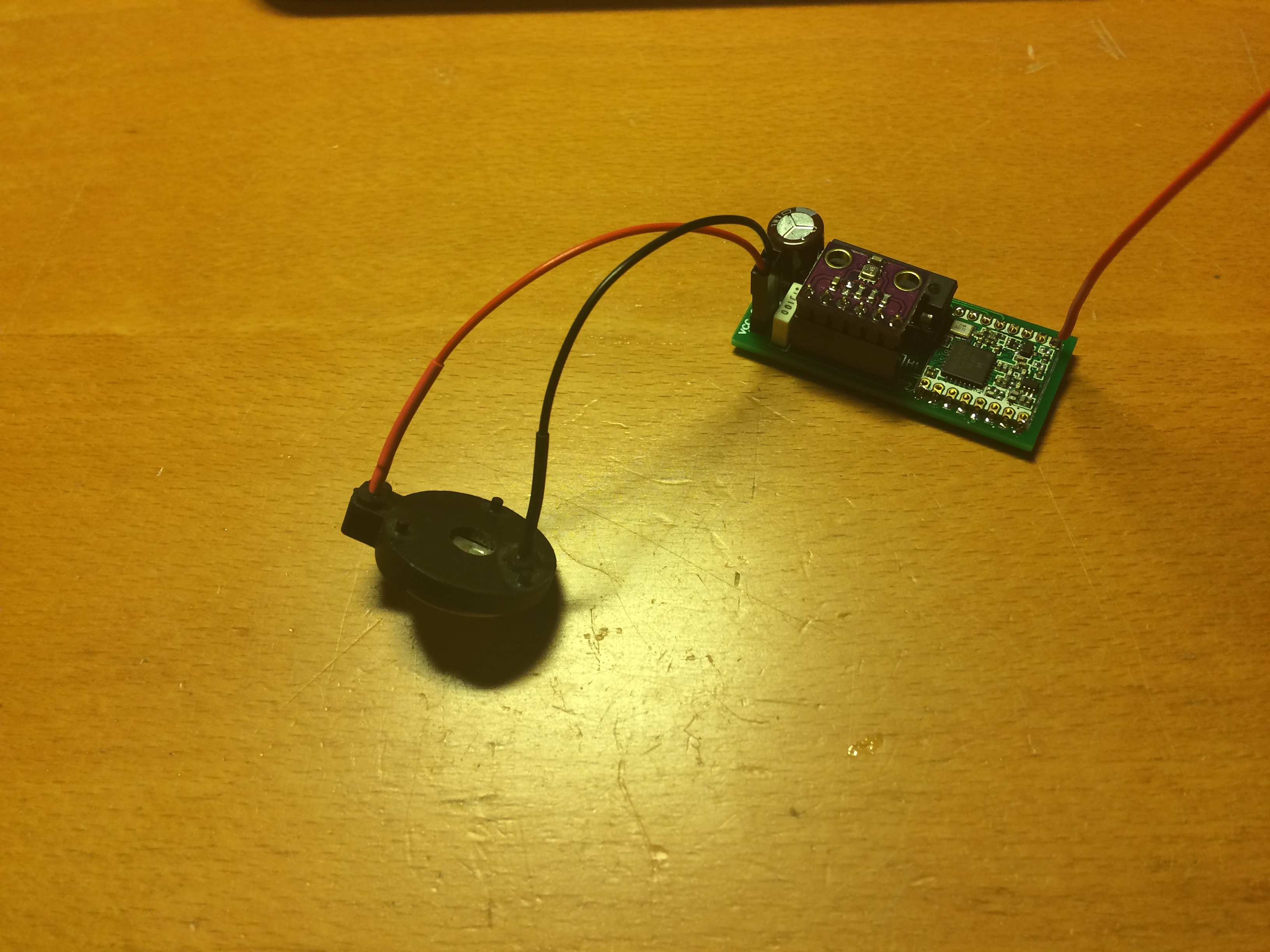
theoretically this is a complete LoRaWAN temp/motion detector node 
*picture updated with smaller capacitor 
1 Like
why such a big capacitor? buffering the current needed while sending?
does it not constantly discharge the battery?
ohhh… he forgot to RTFx ![]()
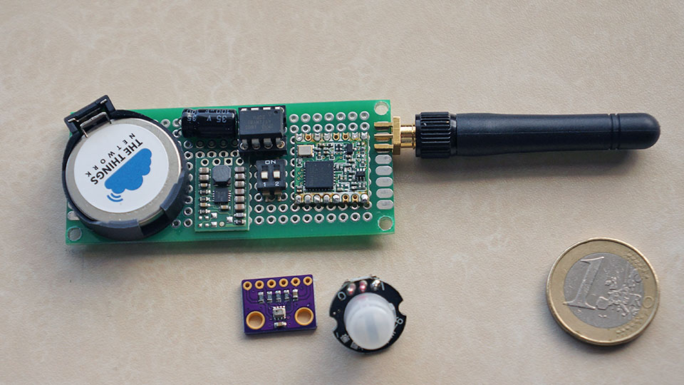
TinyLoRa-BME280 v1.1
I made some improvements based on the feedback from @jym with regard to the hardware interrupt from DIO0 pin.
In v1.1 only PB3 and PB4 from the ATtiny are needed, no hassle with fuse bits changing the reset pin PB5.
I also had some problems with the current of the BME280 drawing 0.6mA in sleep mode.
Now I disable the SPI interface and set the SCK and DO pin as Input and Low before the ATtiny goes in power down mode.
This gives me the promised 0.1uA of the BME280 as written in the data sheet.
The sleep current of the RFM module is 0.5uA.
Most of the power consumes the ATtiny 3,5uA @ 2,8 volt in power down mode so there is still space for improvement.
Will be continued… it’s a race to the bottom. 
8 Likes
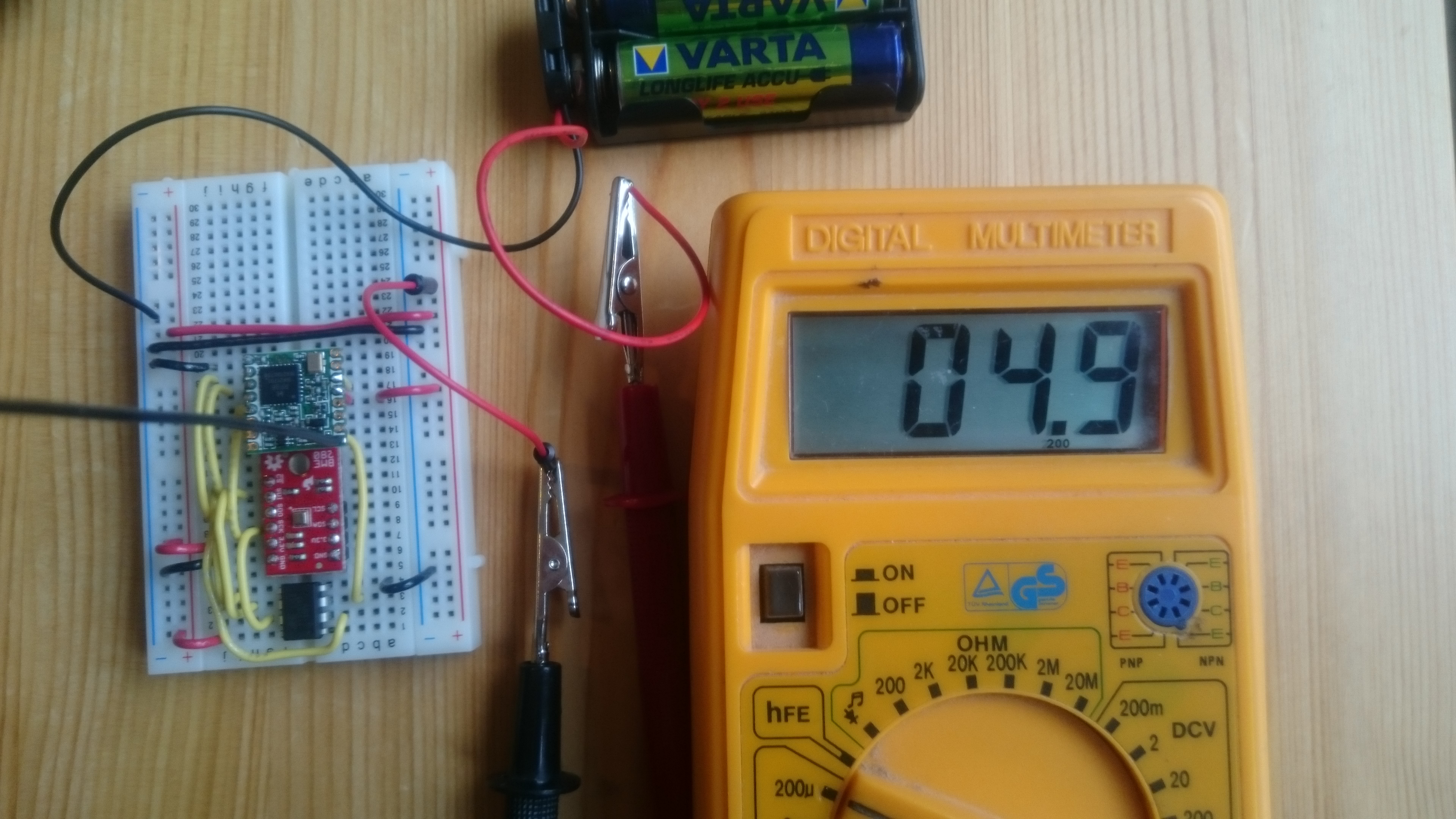
Inspired by this forum, I made a node with ATtiny84 + RFM95W and BME280. I managed to get the current down to 4.8uA in sleep/power down mode. Remember to remove some pull up/pull down resistors on the BME280 bord. Due to the two modes (I2C and SPI) they are on that board. Perhaps you don’t need them all. On my board it used 3.3v/10k = 330uA before I removed one of the SMD resistors.
11 Likes
Great!
attiny85 is cute but I think 84 is much more interesting due to extra pins and cheaper price.
any more details on your implementation ? chance to share code / hw design?
1 Like
Extra pins is indeed the reason I choose this microprocessor and my experience with it of course. I will share my implementation and detail in a Blog I’m starting. I will announce the site here in a few weeks.
2 Likes
great
Due to the positive response I made a new blog in the past week and here is the link to the ATtiny84 low power node:
http://www.iot-lab.org/blog/101/
Have fun!
6 Likes
Good work, I can run on 923MHz now ^^.
before can’t run because I set internal clock 1MHz @_@!.
How I can change connect MOSI–MOSI (PB0),
this point is another waste my time for debug it.
Thank You.
I am having good results testing using an ATtiny85 as a sleep supervisor as it idles at less than 1uA waiting for a hardware interrupt. I have little programming experience however and have trouble making SoftwareSerial library work with the sleep library, anybody try this?
I would like detect an event and then drive a high-side switch using the ATtiny upon wake-up from deep sleep, write the packet counter to a totally powered down (ABP) LoRaWAN node. A serial message would be ideal but I guess I could tap it out in morse! A simple digital indication from the LoRaWAN node after transmit could sleep the node again.
Ideas?
Hi Leo,
great blogpost thank you.
a question
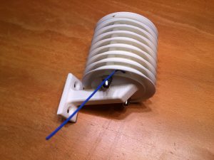
were did you bought this enclosure ?
I did not bought it. I designed and printed it myself (3D print). You only have to add 2x M4 x 60mm bolts and 2x M4 nuts.
I made the design public available: http://a360.co/2FBE9M9. You have to print the mid-section a few (8) times.
I learned that it is called Stevenson screen. My design has the looks but not the scientific usability 
aha… another reason to buy / build a 3d printer ![]()
I put your link in the new 3D printer topic tnx
1 Like
/i/71802/products/2015-05-31T02%3A37%3A29.395Z-IMG_5261.JPG)