Big ESP32 / SX127x topic part 1

Sorry for the late reply… on RANGE:

  • Has anyone managed to get better than 30m range on 868Mhz?
    I have the TTGO not the Heltec, so doesn’t really have any good labelling on the board. Someone on the facebook group suggested that the SX1276 chipset may be connected up incorrectly to the aerial - i.e. to the 433mhz output, not the 868 output; thus the terrible range! I can’t check until I’m in the lab with the right magnifying equipment next week.
  • The aeriel on my TTGO isn’t the silly coil, it’s a stubby GSM-style aerial - with a cable (which are liable to break also!)
    For reference, it’s this one:
    https://goo.gl/nsTvn8
    image

How did you test your IPEX cables? A simple multimeter resistance test between both ends of the center pin show infinite… probably not good. Unfortunately i don’t have a spare one to test with currently.

I’ve got this one. Range was a problem. It turns out that I broke the cable.
I tested it tonight with the Lopy Antenna. I got to 500 meters, connecting to my single channel Lopy gateway, meaning that more range is not likely. I could not test it with the provided antenna because the connector size is just a bit bigger.
But there is probably nothing wrong with the connections on the board itself.

p.s. by accident today I learned that the Pin diagram provided by this seller is incorrect. just look at the print on the board (on the back). :slight_smile:

1 Like

Same here. I pulled replacement cables out of an old wireless router to compare. They did have center pins connected :slight_smile: Admittedly, at that point I did not even think that strictly speaking a cable does not have to be a straight wire, but I suppose that would make it way more pricey for no real benefit.

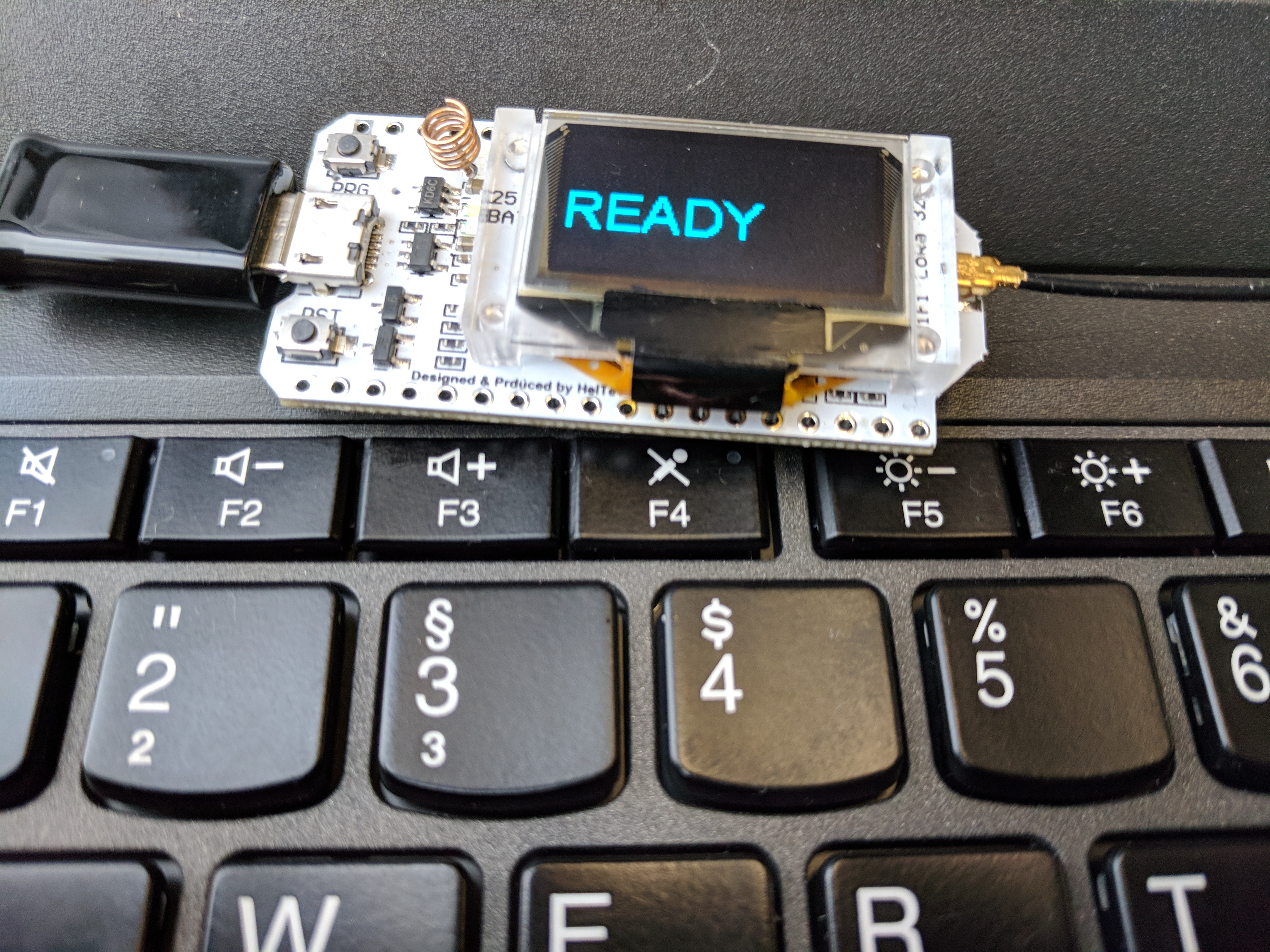
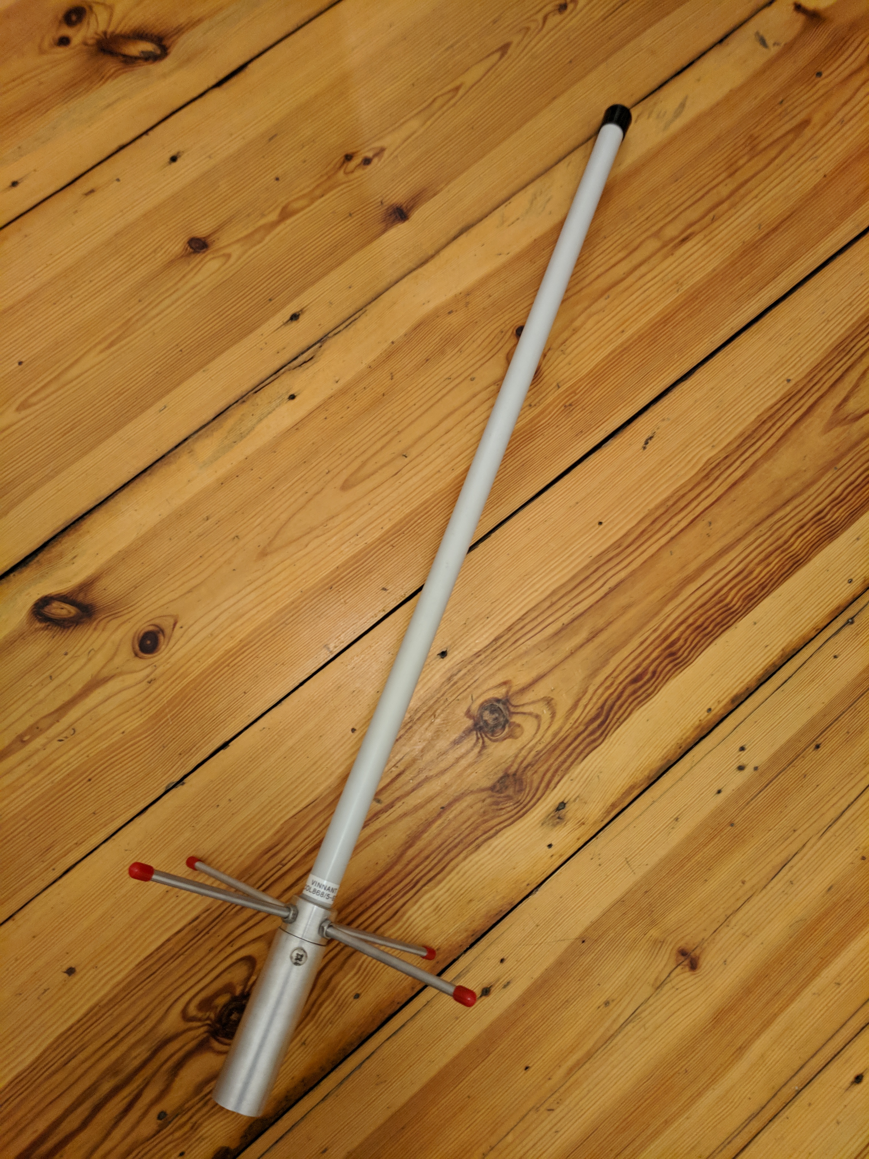
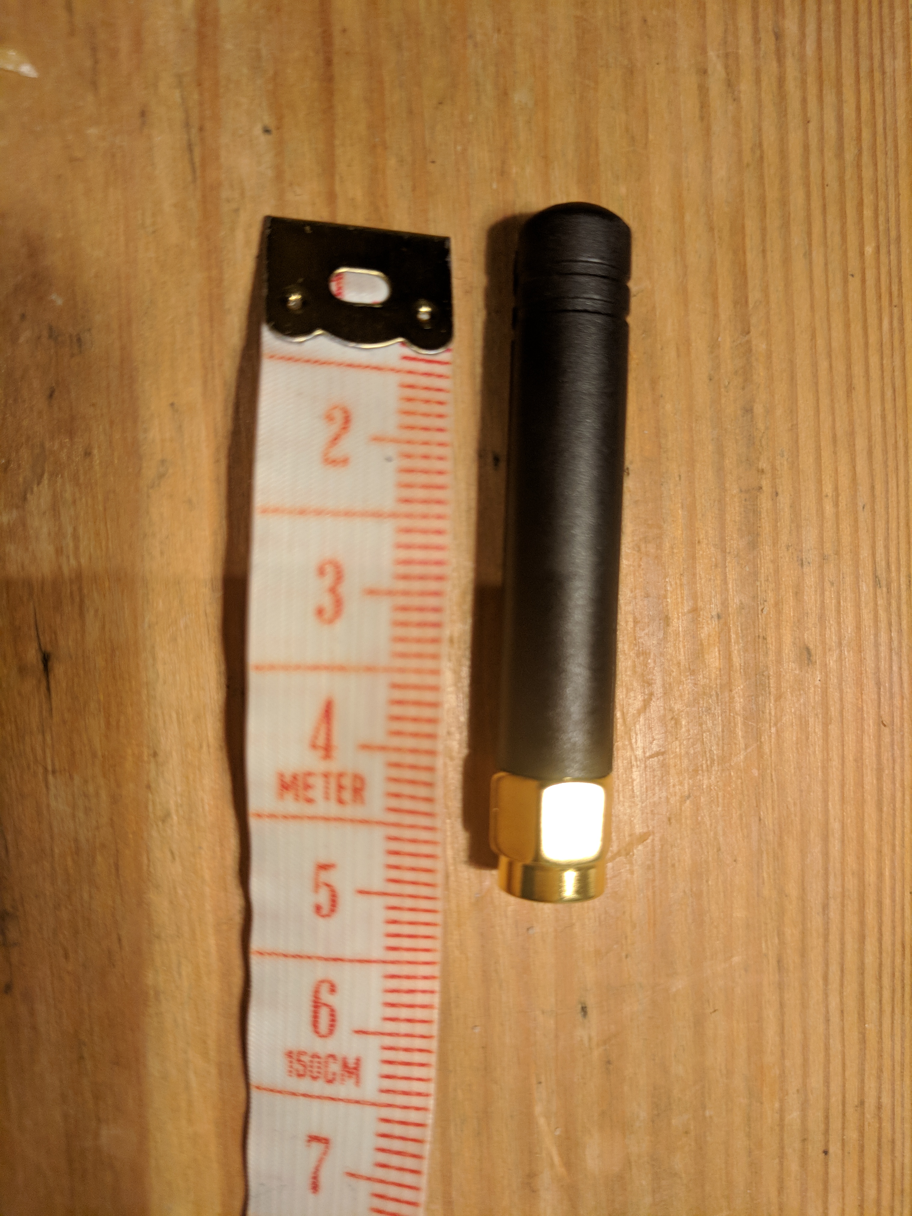
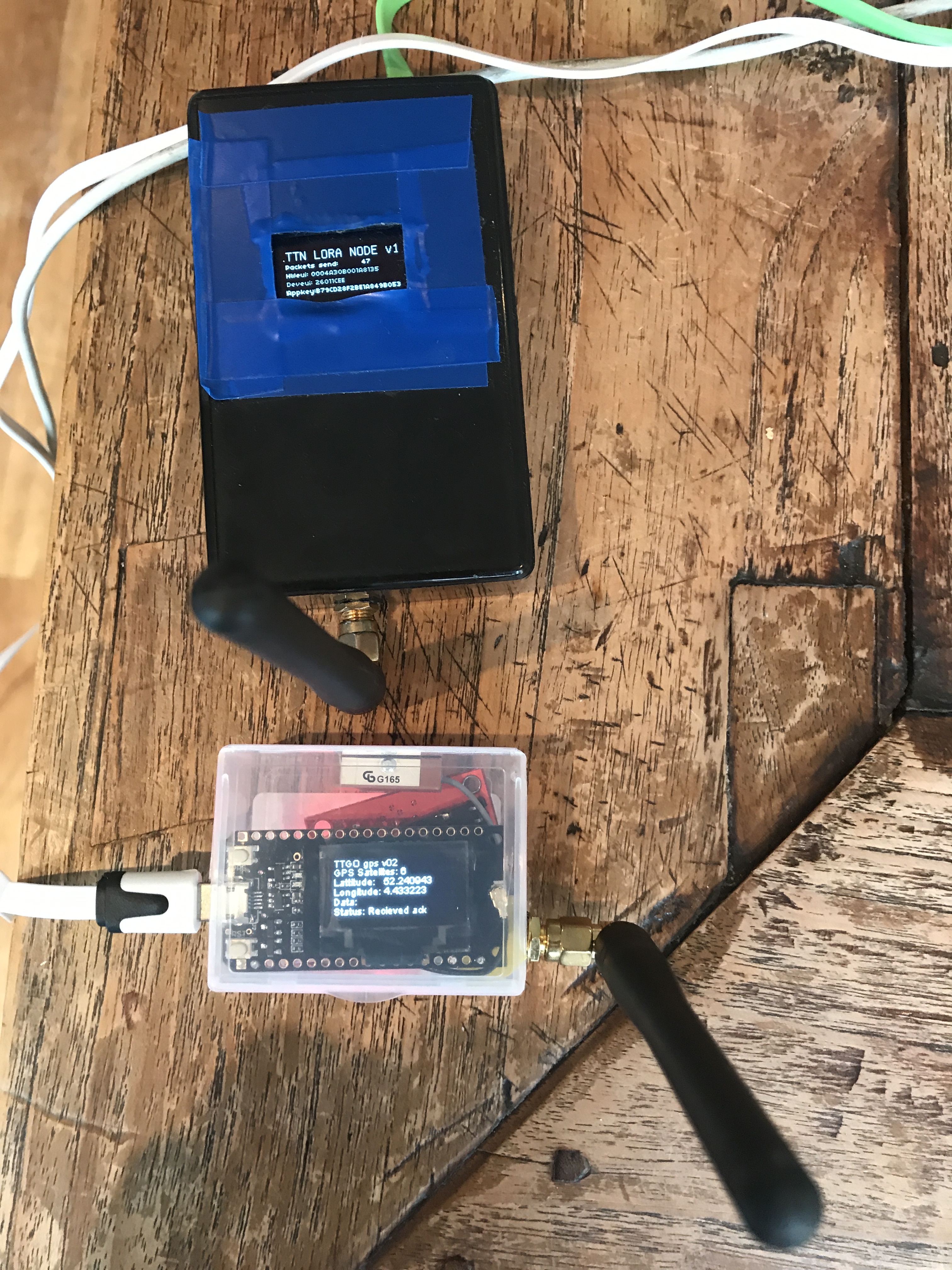
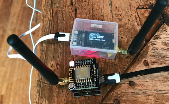
Been testing the TTGO in house and get terrible range also. Checked with my TTN UNO and WITTY / RFM95 with same antenna’s and got these results;

IMG_2583
54

TTGO:
{
“gw_id”: “eui-008000000000a46d”,
“payload”: “QKURASaAAAABy1DLm4cPL1CMwjECeSQ=”,
“lora”: {
“spreading_factor”: 7,
“bandwidth”: 125,
“air_time”: 61696000
},
“coding_rate”: “4/5”,
“timestamp”: “2018-01-13T11:31:14.313Z”,
"rssi": -117,
"snr": -2.5,
“dev_addr”: “260111A5”,
“frequency”: 868500000
}

TTN UNO:
{
“gw_id”: “eui-008000000000a46d”,
“payload”: “QO4cASYABgAB+JSG6vU=”,
“f_cnt”: 6,
“lora”: {
“spreading_factor”: 7,
“bandwidth”: 125,
“air_time”: 46336000
},
“coding_rate”: “4/5”,
“timestamp”: “2018-01-13T11:34:29.172Z”,
"rssi": -67,
"snr": 8.5,
“dev_addr”: “26011CEE”,
“frequency”: 868500000
}

WITTY / RFM95;
{
“gw_id”: “eui-008000000000a46d”,
“payload”: “AD+SANB+1bNw8Fq0DFuYiACqDyK/8Vc=”,
“dev_eui”: “0088985B0CB45AF0”,
“lora”: {
“spreading_factor”: 7,
“bandwidth”: 125,
“air_time”: 61696000
},
“coding_rate”: “4/5”,
“timestamp”: “2018-01-13T11:49:26.374Z”,
"rssi": -72,
"snr": 9.8,
“app_eui”: “70B3D57ED000923F”,
“frequency”: 868300000
}

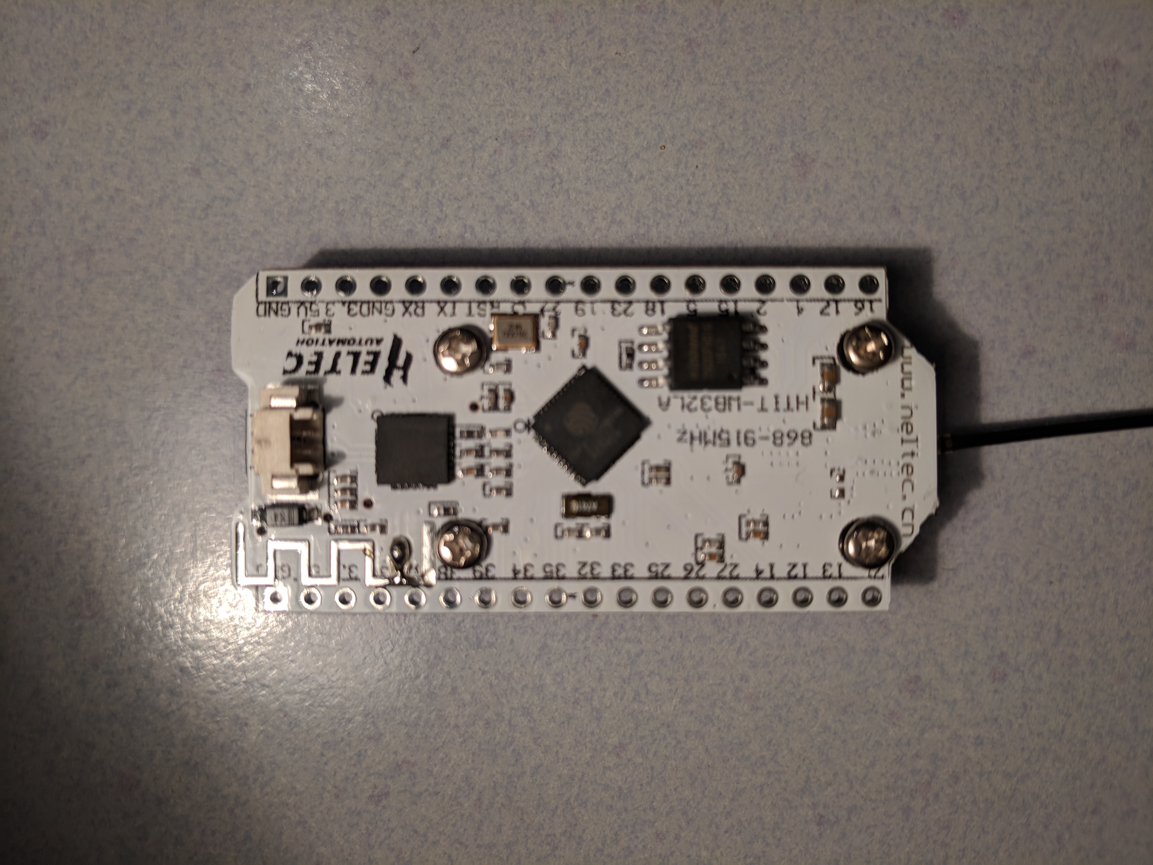
Seems the TTN UNO and RFM95 outperform the TTGO by far. Something must be wrong in this module.

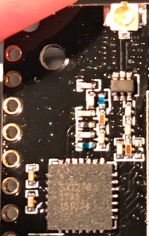
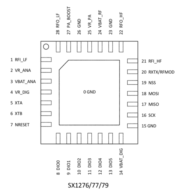
Checked the pcb path of SX1276 to antenna and seems to be ok (connected to RFI_HF);

ttgo board sx1276

50

I rewrote my initial post in English and added one explaining how to connect a DHT11 sensor
First post (also details the setup part)
Second post with the actual sensor setup.

I’ll do one more with a bit more complex sensor.

While doing this, I noticed that the pin diagram the listing page at Aliexpress is incorrect.You can check at the back of the board. For my board it should look like this:
ESP32_pinout_correct

1 Like

nice work. but: 500 m is not much. we expect up to 5 km…

I know, need to find a real / full gateway to test against. When I drove around Helmond (where a couple are), the antenna cable was probably already broken, so no results there the first time.

1 Like

I tested and compared 2 boards, both labelled “Heltec Automation”, but ordered from different sellers on Amazon (seller names DIYmall and MakerHawk).

One board has a coil antenna for Wifi on the top side, the other one has a spare in this place. Both boards also have a small pcb antenna on the bottom side, but it is not connected on both boards.

That means that the board with the missing coil has no active wifi antenna at all. That makes no sense. So i corrected this by placing a small drop of solder connecting the pcb’s coil pinout with the pcb antenna.

After this correction was done i compared Wifi RX performance of both boards, putting them outside in a medium busy area, placed near to each other. Then sniffed MAC frames in monitor mode, filtered unique MAC addresses, count them 4 minutes and finally compare the results. Same for Bluetooth, counting over 30 seconds.

Result was, that the board with coil antenna sees about 3 times more MAC and BLE frames, than the board with the pcb antenna.

It seems the coil antenna does it’s task much better than the pcb antenna, and obviously the coil- and the pcb antennas are both used for Wifi and BLE in parallel.

Then i tested LoRa RX/TX performance with two different antennas. I used the enclosed mini rubber antenna (length ~4cm) and i used a 5dBm DIY 868 MHz groundplane antenna. The rssi level difference after OTAA connecting to a gateway with SF9 in 2km distance on a high tower is about 10 (-108 to -98), and the absolute rssi value is comparable with other i nodes i tried in the same place.

So it seems, that the RF performance of both boards is identical, and on the same level as with other LoRa nodes i tested. The enclosed mini rubber antenna seems to work suprisingly good. The difference compared to my groundplane is far less than i expected.

IMG_20171226_115119
IMG_20180114_180717
IMG_20180112_184137
IMG_20180109_200704

2 Likes

and the position of the non coil pcb antenna board… horizontal or vertical polarisation ? does that make any difference ?

how can i find out polarization of a pcb antenna?

its the position of the pcb in this case

I think polarization is not an issue in this case, because the sniffed Wifi- and BLE signals come from moving smartphones.

Here’s a picture of my tiny DIY node with 3D printed case, housing an Heltec LoRa-32 board and a 500mAh Li-Ion battery.

IMG_20180114_201032

So it sounds like the TTGO does have a consistent problem - with a bunch of us having bought from Lilygo - and we’re disputing with Aliexpress. But Lily from LilyGo is trying to help out in the facebook forum on this issue.

Thanks for the pin-out check @piair - someone on the facebook group mentioned something about maybe the aerial is connected to / matched to a 433Mhz output rather than 868Mhz? Do you have the skills/knowledge to figure that out?

I’m sitting here with an oscilliscope, mulitimeter and magnifying glass… but have NO idea what to do :thinking:

Hi,

I have 3 of the same boards (but with coil-antennas). Could you share the code so I can test this also?

THNX

see my previous post on the connection. dont have a microscope (but good eyes) and looks like it is connecties to the wright pins on the sx1276.

That means, Pin21/22 are connected?

21 RFI_HF (GND) I (-) RF input for band 1 (Ground)
22 RFO_HF (GND) O (-) RF output for band 1 (Ground)

The code is currently skeleton-like and it would cause licence issues if i would post it here. Sorry…

I also have NO idea how to test. I figured that because I was able to get 500 meters reach in combination with a single channel gateway, it should be OK. Would it be able to do that if the aerial is connected to the wrong output?