It seems there is a new Version 2 of TTGO boards upcoming on AliExpress. I found the enclosed change log table for it.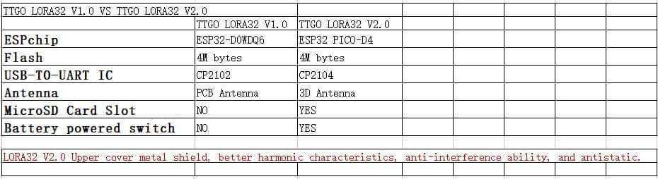
2 Likes
Using the PICO-D4 is a good idea. Much less to go wrong since much of ancillaries are integrated into the chip 
Hi @88bit -
Be sure that you have APPEUI and DEV EUI in LSB format as imported from your device in TTN. Then be sure you have APPKEY as well, in MSB format.
I don’t see APPEUI in your code. Maybe a cut and paste thing.
I hope this helps.
Github: TTGO V2 LilyGo
1 Like
The version 1 is what we are using. Version 2 is already available on alliexpres.
https://nl.aliexpress.com/item/1-Stks-TTGO-LORA32-V2-0-868-915-Mhz-ESP32-LoRa-OLED-0-96-Inch-Sd/32847471775.html
I will post Part 2 of this topic today with pictures of the different Heltec and TTGO boards (V2 included).
I am looking for answers to the following for the part 2 post:
- Do the TTGO boards (with display) use the same pin mappings as the Heltec boards?
- Do the TTGO boards also have all DIO0, DIO1 and DIO2 connected like the Heltec?
(Pinout diagrams from both Heltec and TTGO do not mention about DIO1 and DIO2). - Does the battery LED on the TTGO behave similar to the Heltec?
(Flashes when no battery connected and powered via USB or 5V pin, does not light when powered via 3.3V pin.)
I don’t have a TTGO board yet, so I cannot test it.
1 Like
Meanwhile i checked the pin connection between SX1276 chip and ESP32 GPIOs on two “Heltec” Boards: No. 1 has coil antenna for wifi and ESP32 CPU Revision 1. No. 2 has no coil antenna for wifi (but the unconnected pcb antenna) and ESP32 CPU Revision 0.
It came out: both boards have same pin configuration, i checked this with a multimeter. pin mappings see below.
But LMiC does not run on board no. 2. As soon as a packet is to be transmitted, LMiC runs on error and crashes. I guess the SPI communication goes wrong, or there is some issue with the SX1276.
I dismounted the OLED display on both boars to check the RF chip version. Both boards have an RF chip labelled “SX1276”.
Pin mappings:
// Hardware pin definitions for Heltec LoRa-32 Board with Semtech SX1276 Chip
#define SS 18 // ESP32 GPIO18 (Pin18) – SX1276 NSS (Pin19) SPI Chip Select Input
#define MOSI 27 // ESP32 GPIO27 (Pin27) – SX1276 MOSI (Pin18) SPI Data Input
#define MISO 19 // ESP32 GPIO19 (Pin19) – SX1276 MISO (Pin17) SPI Data Output
#define SCK 5 // ESP32 GPIO5 (Pin5) – SX1276 SCK (Pin16) SPI Clock Input
#define RST 14 // ESP32 GPIO14 (Pin14) – SX1276 NRESET (Pin7) Reset Trigger Input
#define DIO0 26 // ESP32 GPIO26 (Pin15) – SX1276 DIO0 (Pin8) used by LMIC for detecting LoRa RX_Done & TX_Done
#define DIO1 33 // ESP32 GPIO33 (Pin13) – SX1276 DIO1 (Pin9) used by LMIC for detecting LoRa RX_Timeout
#define DIO2 32 // ESP32 GPIO32 (Pin12) – SX1276 DIO2 (Pin10) not used by LMIC for LoRa (Timeout for FSK only)// Hardware pin definitions for Heltec LoRa-32 Board with OLED SSD1306 I2C Display
#define OLED_RST 16 // ESP32 GPIO16 (Pin16) – SD1306 Reset
#define OLED_SDA 4 // ESP32 GPIO4 (Pin4) – SD1306 Data
#define OLED_SCL 15 // ESP32 GPIO15 (Pin15) – SD1306 Clock
1 Like
this topic is full … thanks everyone
we continue here BIG ESP32 / SX127xtopic part 2
1 Like