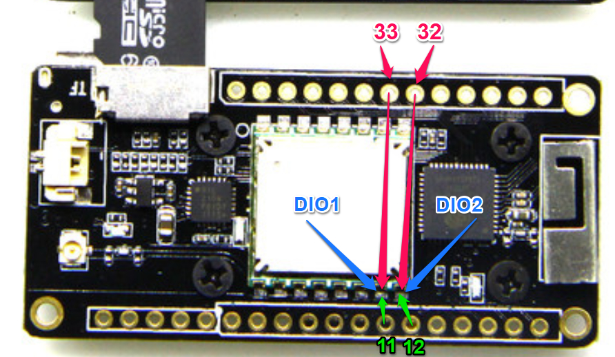
You are free to select any possible free GPIO for connecting DIO1 and DIO2.
But using GPIO33 and GPIO32 keeps it consistent with Heltec and the older TTGO’s so less hassle for looking up differences and modifying configuration settings.
I checked with my multimeter in continuity mode, looks like they are connected as indicated in green on the picture and that’s strange because schematic does not mention that connection except IO12 connected to SD DAT2.
The board PINS are indeed connected as indicated by the green arrows (DIO1 and DIO2), but the green numbers are nonsense. Those pins are not connected to GPIO11 or GPIO12.
This was already documented in the topic start and in my custom version of the pinout diagram.
Hello, I connect LoRa ESP32 SX1276 with LoRaWan. Maybe you know how I can measure data transfer speeds? I measured the distance to the station with ttn map. Maybe someone help me?
The ttn console captures the airtime and the payload size of a particular uplink or downlink - from that you can calculate the speed of transfer if it’s what you meant by speed.
I use the Heltec board for some time now and really happy with it the one thing that I can identify still is there any internal connection with voltage divider from the battery to analog pin like in the other development boars with Li battery ?
e.g. I want to be able to measure the battery voltage easily …
There seem to be quite a few boards of this type which dont provide access to read the battery voltage.
Its a significant omission, to use LiPo batteries safely, and for long life, you need to stop using them when the voltage has fallen to 3.0V or so. This is obviously difficult if you have no provided means of reading the battery voltage.
It is also difficult to stop using power if the board does not provide a ‘switch off’ option so external hardware is required anyway. Why not include a voltage measurement at that point?
As i can see from datasheet SX1278 supports OOK tx and rx mode, but i haven’t found the right way how to do this. Are there any sample sketch how this can be done?
Hi,
i have a Heltec 868 Mhz V2 (Pinout: http://www.heltec.cn/download/WIFI_LoRa_32_Diagram.pdf) and an old Garmin Geko 201. The Garmin Geko has a RS232 interface which i want to connect to the Heltec Device. I use a MAX3232 Converter for RS232 to TTL and the Geko sends its data as MNEA 0183 format. I have found a simple GPS library (http://arduiniana.org/libraries/tinygpsplus) to decode the data. My problem is, that the library uses soft serial to get the data from any pin (4800 Baud) on the ESP. But soft serial is not available for the ESP32 and so i think i can use hardware serial, an ESP has 3 UART so it should normally no problem, but which pins can i use? i have read the docs that Serial1 uses pin 9 and 10, but this pins are not existing on the Heltec board. Serial2 uses pin 16 and 17. Pin 17 is also used by the oled display, so it can be a problem to use this pins. I guess Serial with pin 1 and 3 will be used for communication with the usb port for example the Arduino IDE monitor so not usable for my use case. Has anybody an idea what can i use or do?