Also be aware of correct pin mapping. The SX1276 chips features two RF_out and two RF_in pins, one for low frequency band (e.g. 33 MHz), and one for high frequency band (e.g. 868 and 915 MHz). So you need a board with proper wiring for your selected frequency. Usually 433 MHz and 868/915 MHz boards cannot be swapped for this reason.
I’ve a TTGO LoRa32 v2.0, and once a LoRa packet is sent, the program hangs, outputting “WAITING” on USB serial monitor, and staying at that state forever.
Do you experience something similar?
I use:
const lmic_pinmap lmic_pins = {
.nss = 18,
.rxtx = LMIC_UNUSED_PIN,
.rst = 14,
.dio = {26, 33, 32},
Thanks for your help.
1 Like
If it should work for you, I would like to tell us about range! Thx!
- What USB serial monitor, from Arduino IDE?
- Where does “WAITING” come from?
The string is not in LMIC-Arduino or its ttn-abp.ini and ttn-otaa.ini examples nor have I seen it in Arduino and PlatformIO serial monitors. - Do you see anything at all on serial monitor?
- Do you output anything on the OLED display?
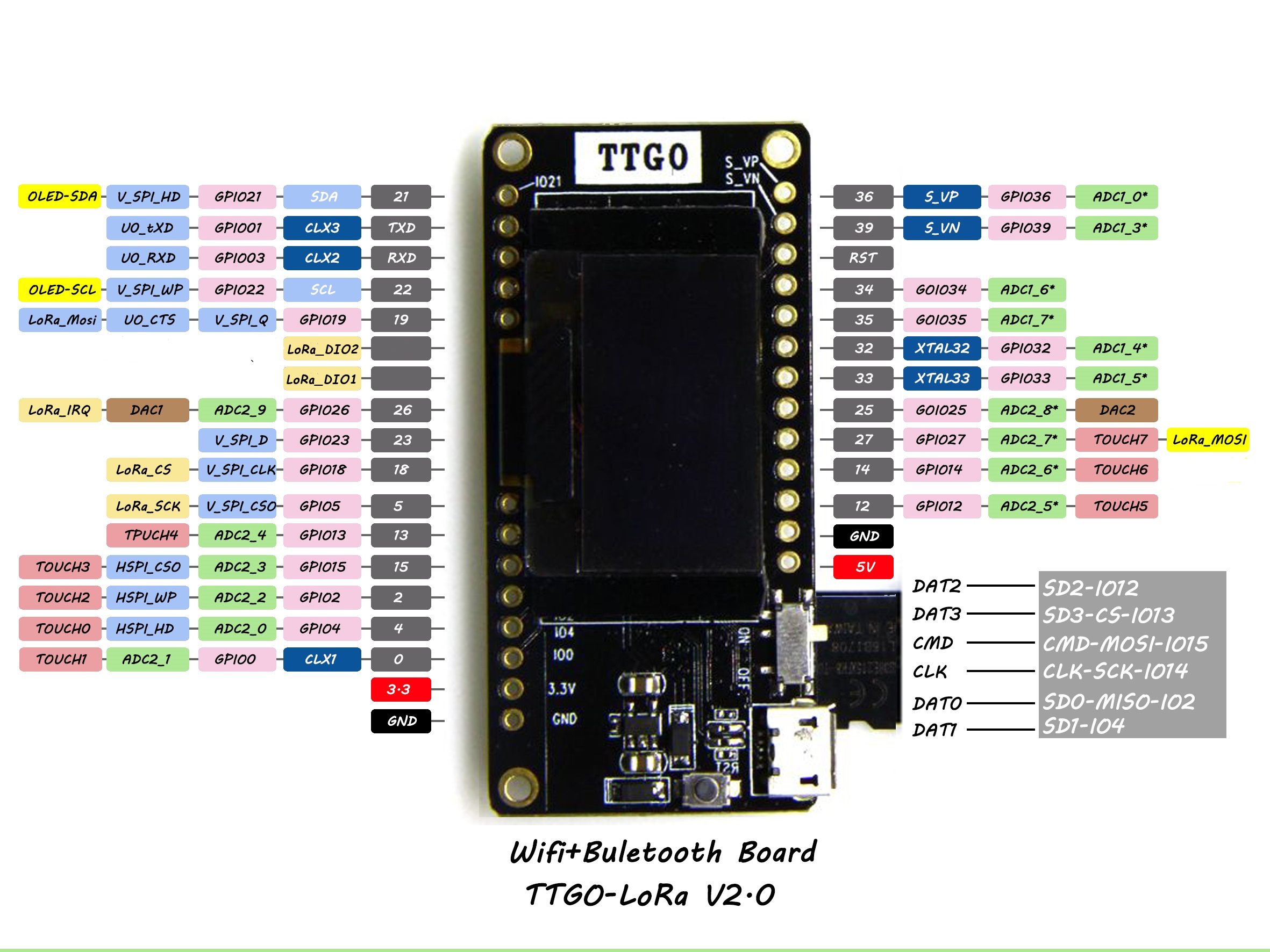
- Have you connected pin marked ‘11’ in the pinout diagram to gpio33 pin and pin marked ‘12’ to gpio32 pin? (See previous posts for explanation.)
yes, this one
I don’t know where the string is coming from. Here is what I see on serial monitor:
rst:0x1 (POWERON_RESET),boot:0x13 (SPI_FAST_FLASH_BOOT)
configsip: 188777542, SPIWP:0xee
clk_drv:0x00,q_drv:0x00,d_drv:0x00,cs0_drv:0x00,hd_drv:0x00,wp_drv:0x00
mode:DIO, clock div:1
load:0x3fff0010,len:4
load:0x3fff0014,len:812
load:0x40078000,len:0
load:0x40078000,len:10164
entry 0x400789f8
Test (template version: 26Dec2016 generated: 12Jan2018 modified 12Jan2018)
BME280 detected!
 temp Celcius:21.92 temp Fahrenheit:71.46 pressure:1032.81 altitude (meters):-163.67
3694 Sending.. Packet queued
3695 Waiting..
Yep, I output Temperature, humidity, pressure and altitude from the BME280 module, and it is refreshed properly until the LoRa packet is sent, and then, it freezes.
I don’t, but as there’s explanations for different boards, I got lost and thought I didn’t have to do so.
Which ones are these pins? I can see gpio32 and gpio33 on this diagram, but not pin marked “11” and “12” (or I don’t understand where I should look at)
Thanks for your help
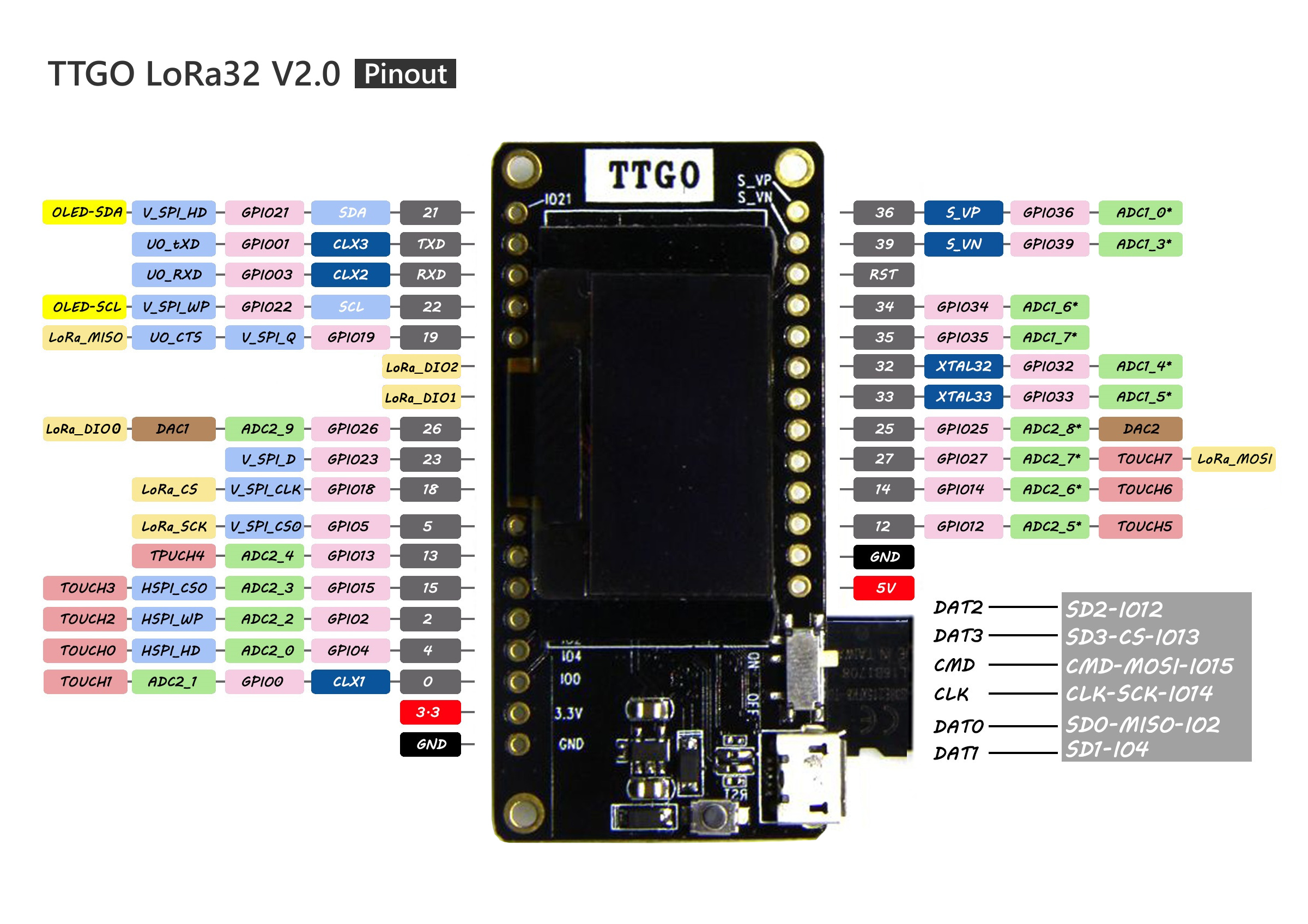
That is the updated pinout diagram from @TKroenert where he removed the ‘11’ and ‘12’ because gpio11 and gpio12 appear not to be connected to these pins (but dio1 and dio2 are).
On the Heltec boards (on V2 at least) and TTGO V1 boards dio1 is connected to gpio33 (pin 33) and dio2 is connected to gpio32 (pin 32), as described in the topic start.
Here is the oiginal TTGO V2 pinout diagram where you can see pins 11 and 12.
For the TTGO V2 you will have to physically connect pin ‘11’ (dio1) to pin 33 (gpio33) and pin ‘12’ (dio2) to pin 32 (gpio32) yourself because they are not wired on-board. (You may wire them to other gpio ports when preferred but then you will have to adjust the pin settings in the software).
Please read above posts for more information.
I suggest to first start with the ttn-abp.ino example sketch from the LMIC-Arduino library, because that is the most basic and will make troubleshooting easier.
Then, when that works you can try the ttn-otaa.ino example sketch for over the air activation.
When you get both these sketches working then you know that the LoRaWAN stuff is working. From there you can start adding features/try other sketches, add temperature sensors etc.
(Note ABP and OTA nodes (‘end devices’) require different configuration settings, both in TTN console and software. See the TTN Console and remarks in the example sketches for more details.)
1 Like
OK that works now. I had some trouble with the BME280 library I was using (that made the sensor values crazy after a few measurements) so I changed it for the grove_BME280 one from Seeed. Everything is OK on this side for now.
A few questions:
-
Does somebody tried to optimise power consumption on the board, using a low power mode or so? And how? Currently, I’m only waiting to send the next packet, and would like to sleep instead for a given time.
-
Do you succeed in using cayenne LPP payload with the board? I tried to switch to that payload but somehow no packet is sent anymore and I got no debug output to investigate.
Thanks for your help!
ESP32 has three modes for deep sleep. The timer function which uses the ULP processor is most easy to implement;
//Serial.println("Bring ESP to sleep mode 2minutes");
/* 5e6 is 5x10^6 microseconds */
ESP.deepSleep(120e6);
some examples; espressif esp32 sleep examples
Aaron, over at Heltec, sent me the library and demo files that that they have:
This is a basic library for point-to-point LoRa communications.
This works with my two Heltec nodes operating one in transmit, and the other in receive. I still, however, have one board that will work with the LMIC library sending to TTN via OTAA, while the other does not.
Same here: two boards, looking identical, but one works with LMiC, the other doesn’t.
LMiC crashes at a point in radio.c, where SPI communication with SX1276 begins. Since the LoRa code from Heltec is running on the board, i assume root cause is not a broken SX1276 chip.
Maybe something with the SPI timing goes wrong, when LMiC operates in dual core environment on ESP32. Unfortunately i cannot try single core mode, since i’m not using the ESP-IDF, but precompiled Ardunio framework.
The reason why this happenes only on certain boards could be production differences in the CPU crystal what has impact on timing.
But this is pure theory so far.
Meanwhile i sent back the non working board to Amazon and got a new one. This works with LMiC, but has a broken, very dim, battery LED and weak RF performance…
2 Likes
Thanks for your help, I will have a look at that. Do you know if there’s a way to detect when USB is connected (to a power supply, not necessarily to a serial console)? I would like to code something like “if USB power supply, then turn screen on, else turn screen off”
I assume with the power hardware on the Heltec (and TTGO?) board it is not possible to see from the CPU from where the 3,3V power comes:
- from battery
- from CP2102 (= USB powered via integrated regulator)
- from USB via regulator on board
So it will only be possible to detect, if a USB data connection is active, and thus the module is powered this way. For this purpose you may open a serial interface with
Serial.begin()
and then use
while serial.available() { turn on screen}
You may take a look in the CP2102 datasheet, but since this chip can be used in different power modes, i guess we need a schematic diagram of the Heltec/TTGO board to answer the question.
I made an update:
TTGO LoRa32 V2.0.pdf (2.4 MB)
Updated: 2018-01-30 21:12 CET some textual fixes.
2 Likes
That library may suffer from the issue I mentioned here;
If so you will see errors on high spreading factor packets.
1 Like
Does anybody know if the TTGO V2 have a ‘display-less’ version like the V1 had ?
Display is nice for prototyping but may become useless once you deploy an unmanaged node in the wild.
I search to be sure of one thing:
When a battery is connected, and you connect the power usb:
It’s good for the heltec card?
Is the battery powered in order to charge it?
How do you charge the battery when you use it?
My auto-answer: 
https://www.thethingsnetwork.org/forum/t/big-esp32-sx127x-topic-part-1/10247/38
Onboard lithium battery charge and discharge circuit, The orange LED lights will go out when the battery is full , only provide the basic lithium battery charging and discharge function, can not monitor the battery temperature and power, if your battery is not purchased in our shop, Please pay attention to the battery positive and negative, wrong operation may explode.
@mrme @Verkehrsrot OK so I did that for ESP deepSleep and using console to power or not the OLED screen. But now I’m running into a deeper problem 
Each time I sleep and wake up, it seems the program restarts from scratch (as counter displayed on screen is not incremented, and ABP packet counter is not incremented neither). Here is the sketch I use:
/* **************************************************************
 * Arduino sketch
 * Author: Martijn Quaedvlieg / Jan de Laet (january 2017)
 * Generated with Generate script by Jan de Laet
 * Modified 12-1-2018 by Pierre Gorissen for use with
 * U8X8 OLED + SX1276
 * Modified 01-2-2018 by Nicolas Derive to use measurements from
 * BME280 sensor and display them on the screen
 * *************************************************************/
#include <SPI.h>

#define BUILTIN_LED 25

// define the activation method ABP or OTAA
#define ACT_METHOD_ABP

// show debug statements; comment next line to disable debug statements
#define DEBUG

#define CFG_eu868

/* **************************************************************
* keys for device (removed for forum posting)
* *************************************************************/
static const uint8_t PROGMEM NWKSKEY[16] = {  };
static const uint8_t PROGMEM APPSKEY[16] = {  };
static const uint32_t DEVADDR = ;

/* **************************************************************
 * user settings
 * *************************************************************/
// Schedule TX every this many seconds (might become longer due to duty
// cycle limitations).
//  const unsigned TX_INTERVAL = 240; // unused

unsigned int countero = 0;
unsigned int serial_act = 0;

unsigned long starttime;
unsigned long cycle_length = TX_INTERVAL * 1000UL; // cycle in secs, currently unused;

// Uses LMIC libary by Thomas Telkamp and Matthijs Kooijman (https://github.com/matthijskooijman/arduino-lmic)
// Pin mappings based upon PCB Doug Larue
#include <lmic.h>
#include <hal/hal.h>

// Declare the job control structures
static osjob_t sendjob;

// These callbacks are only used in over-the-air activation, so they are
// left empty when ABP (we cannot leave them out completely unless
// DISABLE_JOIN is set in config.h, otherwise the linker will complain).
#ifdef ACT_METHOD_ABP
  void os_getArtEui (u1_t* buf) { }
  void os_getDevEui (u1_t* buf) { }
  void os_getDevKey (u1_t* buf) { }
#else
  void os_getArtEui (u1_t* buf) { memcpy_P(buf, APPEUI, 8);}
  void os_getDevEui (u1_t* buf) { memcpy_P(buf, DEVEUI, 8);}
  void os_getDevKey (u1_t* buf) { memcpy_P(buf, APPKEY, 16);}
#endif

/* **************************************************************
 * Pin mapping
 * *************************************************************/
const lmic_pinmap lmic_pins = {
    .nss = 18,
    .rxtx = LMIC_UNUSED_PIN,
    .rst = 14,
    .dio = {26, 33, 32},
};


/* **************************************************************
 * OLED setup
 * *************************************************************/
#include "SSD1306.h"
#include "images.h"

// the OLED used
SSD1306 display(0x3c, 21, 22);
void logo(){
  display.clear();
  display.drawXbm(0,5,logo_width,logo_height,logo_bits);
  display.display();
}

/* **************************************************************
 * Sensor setup
 * *************************************************************/

#include <Wire.h>
//#include "BlueDot_BME280.h"
#include <Seeed_BME280.h>
//BlueDot_BME280 bme280 = BlueDot_BME280();
BME280 bme;
// sensor variables
float tempC = 0.0;
float pressure = 0.0;
float humidity = 0.0;
float altitudeMeter = 0.0;
// meteofrance.fr : "En moyenne, la pression atmosphérique diminue de 1 hPa tous les 8 mètres"
#define ALT 44
#define COR (ALT/8.0)

unsigned int counter = 0;

// data to send
static uint8_t dataTX[8];

/* **************************************************************
 * setup
 * *************************************************************/
void setup() {
  //Set baud rate
  Serial.begin(115200);
  // Wait (max 10 seconds) for the Serial Monitor
  while ((!Serial) && (millis() < 10000)){ }

  init_node();
  init_sensor();

  pinMode(16,OUTPUT);
  pinMode(2,OUTPUT);
  if (Serial) {
    serial_act = 1;
    digitalWrite(16, LOW);    // set GPIO16 low to reset OLED
    delay(50);
    digitalWrite(16, HIGH); // while OLED is running, must set GPIO16 in high
    display.init();
    display.flipScreenVertically();
    display.setFont(ArialMT_Plain_10);
    logo();
    delay(1500);
  }
  else {
    digitalWrite(16, LOW);
  }
  }
  starttime = millis();
}


/* **************************************************************
 * loop
 * *************************************************************/
void loop() {
      do_sense();

      // check if need to send
      build_data();
      do_send();
//      delay(240000);
//  if ((millis() - starttime) > cycle_length) { build_data(); do_send(); starttime = millis(); } // don't know how to rewrite this with ESP deepsleep
      Serial.println("Bring ESP to sleep mode 5minutes");
/* 5e6 is 5x10^6 microseconds */
      ESP.deepSleep(240e6);
}


/* **************************************************************
 * sensor code, typical would be init_sensor(), do_sense(), build_data()
 * *************************************************************/
/* **************************************************************
 * init the sensor
 * *************************************************************/
void init_sensor() {
    while (!bme.init()){
      Serial.print("BME280 error!");
    delay(2000);
    }
}

/* **************************************************************
 * do the reading
 * *************************************************************/
void do_sense() {

  // Read temperature as Celsius (the default)
  tempC = bme.getTemperature();
  // Read humidity
  humidity = bme.getHumidity();
  // Read the pressure in hPa
  pressure = bme.getPressure();
  // Read the altitude in Meters
  altitudeMeter = bme.calcAltitude(pressure);
  pressure = pressure/100;

  // Check if any reads failed and exit early (to try again).
  if (isnan(pressure) || isnan(tempC) || isnan(humidity) || isnan(altitudeMeter)) {
    #ifdef DEBUG
      Serial.println("Failed to read from BME280 sensor!");
    #endif
    return;
  }
  if (serial_act == 1) {
  display.clear();
  display.setTextAlignment(TEXT_ALIGN_LEFT);
  display.setFont(ArialMT_Plain_10);
  //u8x8.setCursor(0, 3);
  //u8x8.printf("Temp: %.1fC", tempC);
  String tempS = "Température : " + String(tempC) + "°C";
  display.drawString(0, 1, tempS);
  String humidityS = "Humidité : " + String(humidity) + "%";
  display.drawString(0, 12, humidityS);
  //u8x8.setCursor(0, 5);
  // u8x8.printf("Press: %.1fhPa", pressure);
  String presS = "Pression : " + String(pressure) + "hPa";
  display.drawString(0, 23, presS);
  String alt = "Altitude : " + String(altitudeMeter) + "m";
  display.drawString(0, 34, alt);
  String counters = "Paquets envoyés : " + String(countero);
  display.drawString(0, 45, counters);
  display.display();
  }
  #ifdef DEBUG
    Serial.print(F(" temp Celcius:"));
    Serial.print(tempC);
    Serial.print(F(" humidity:"));
    Serial.print(humidity);
    Serial.print(F(" pressure:"));
    Serial.print(pressure);
    Serial.print(F(" altitude (meters):"));
    Serial.print(altitudeMeter);
    Serial.println(F(""));
  #endif
  delay(2000);
}

/* **************************************************************
 * build data to transmit in dataTX
 *
 * Suggested payload function for this data
 *
 * function Decoder(bytes, port) {
 * var temp = parseInt(bytes[0] + (bytes[1] << 8 ) - 500) / 10 ;
 * var humidity = parseInt(bytes[2] + (bytes[3] << 8 ) ;
 * var pressure = parseInt(bytes[4] + (bytes[5] << 8 )) / 10;
 * // don't know why, but in my case the altitude was about 90 meter to low, so added 90 meters
 * var altitude = parseInt(bytes[6] + (bytes[7] << 8 ) - 100) / 10;
 * return { temp: temp,
 *        humidity: humidity,
 *        pressure: pressure,
 *        altitude: altitude
 * };
* }
 * *************************************************************/
void build_data() {

  int dtempC = (tempC + 50) * 10;
  int dpressure = pressure * 10;
  int daltitude = (altitudeMeter + 100)  * 10;
  dataTX[0] = dtempC;
  dataTX[1] = dtempC >> 8;
  dataTX[2] = int(humidity);
  dataTX[3] = int(humidity) >> 8;
  dataTX[4] = dpressure;
  dataTX[5] = dpressure >> 8;
  dataTX[6] = daltitude;
  dataTX[7] = daltitude >> 8;
}

/* **************************************************************
 * radio code, typical would be init_node(), do_send(), etc
 * *************************************************************/
/* **************************************************************
 * init the Node
 * *************************************************************/
void init_node() {
  #ifdef VCC_ENABLE
     // For Pinoccio Scout boards
     pinMode(VCC_ENABLE, OUTPUT);
     digitalWrite(VCC_ENABLE, HIGH);
     delay(1000);
  #endif

  // LMIC init
  os_init();
  // Reset the MAC state. Session and pending data transfers will be discarded.
  LMIC_reset();

  #ifdef ACT_METHOD_ABP
    // Set static session parameters. Instead of dynamically establishing a session
    // by joining the network, precomputed session parameters are be provided.
    #ifdef PROGMEM
      // On AVR, these values are stored in flash and only copied to RAM
      // once. Copy them to a temporary buffer here, LMIC_setSession will
      // copy them into a buffer of its own again.
      uint8_t appskey[sizeof(APPSKEY)];
      uint8_t nwkskey[sizeof(NWKSKEY)];
      memcpy_P(appskey, APPSKEY, sizeof(APPSKEY));
      memcpy_P(nwkskey, NWKSKEY, sizeof(NWKSKEY));
      LMIC_setSession (0x1, DEVADDR, nwkskey, appskey);
    #else
      // If not running an AVR with PROGMEM, just use the arrays directly
      LMIC_setSession (0x1, DEVADDR, NWKSKEY, APPSKEY);
    #endif

    #if defined(CFG_eu868)
      // Set up the channels used by the Things Network, which corresponds
      // to the defaults of most gateways. Without this, only three base
      // channels from the LoRaWAN specification are used, which certainly
      // works, so it is good for debugging, but can overload those
      // frequencies, so be sure to configure the full frequency range of
      // your network here (unless your network autoconfigures them).
      // Setting up channels should happen after LMIC_setSession, as that
      // configures the minimal channel set.
      // NA-US channels 0-71 are configured automatically
      LMIC_setupChannel(0, 868100000, DR_RANGE_MAP(DR_SF12, DR_SF7),  BAND_CENTI);      // g-band
      LMIC_setupChannel(1, 868300000, DR_RANGE_MAP(DR_SF12, DR_SF7B), BAND_CENTI);      // g-band
      LMIC_setupChannel(2, 868500000, DR_RANGE_MAP(DR_SF12, DR_SF7),  BAND_CENTI);      // g-band
      LMIC_setupChannel(3, 867100000, DR_RANGE_MAP(DR_SF12, DR_SF7),  BAND_CENTI);      // g-band
      LMIC_setupChannel(4, 867300000, DR_RANGE_MAP(DR_SF12, DR_SF7),  BAND_CENTI);      // g-band
      LMIC_setupChannel(5, 867500000, DR_RANGE_MAP(DR_SF12, DR_SF7),  BAND_CENTI);      // g-band
      LMIC_setupChannel(6, 867700000, DR_RANGE_MAP(DR_SF12, DR_SF7),  BAND_CENTI);      // g-band
      LMIC_setupChannel(7, 867900000, DR_RANGE_MAP(DR_SF12, DR_SF7),  BAND_CENTI);      // g-band
      LMIC_setupChannel(8, 868800000, DR_RANGE_MAP(DR_FSK,  DR_FSK),  BAND_MILLI);      // g2-band
      // TTN defines an additional channel at 869.525Mhz using SF9 for class B
      // devices' ping slots. LMIC does not have an easy way to define set this
      // frequency and support for class B is spotty and untested, so this
      // frequency is not configured here.
    #elif defined(CFG_us915)
      // NA-US channels 0-71 are configured automatically
      // but only one group of 8 should (a subband) should be active
      // TTN recommends the second sub band, 1 in a zero based count.
      // https://github.com/TheThingsNetwork/gateway-conf/blob/master/US-global_conf.json
      LMIC_selectSubBand(1);
    #endif

    #if defined(DEBUG)
      LMIC_disableChannel(1);
      LMIC_disableChannel(2);
      LMIC_disableChannel(3);
      LMIC_disableChannel(4);
      LMIC_disableChannel(5);
      LMIC_disableChannel(6);
      LMIC_disableChannel(7);
      LMIC_disableChannel(8);
    #endif

    // Enable data rate adaptation
    // LMIC_setAdrMode(1);

    // Disable link check validation
    LMIC_setLinkCheckMode(0);

    // TTN uses SF9 for its RX2 window.
    LMIC.dn2Dr = DR_SF9;

    // Set data rate and transmit power (note: txpow seems to be ignored by the library)
    LMIC_setDrTxpow(DR_SF7,14);
  #endif

  #ifdef ACT_METHOD_OTAA
    // got this fix from forum: https://www.thethingsnetwork.org/forum/t/over-the-air-activation-otaa-with-lmic/1921/36
    LMIC_setClockError(MAX_CLOCK_ERROR * 1 / 100);
  #endif

}

/* **************************************************************
 * send the message
 * *************************************************************/
void do_send() {

  Serial.print(millis());
  Serial.print(F(" Sending.. "));

  send_message(&sendjob);

  // wait for send to complete
  Serial.print(millis());
  Serial.print(F(" Waiting.. "));

  while ( (LMIC.opmode & OP_JOINING) or (LMIC.opmode & OP_TXRXPEND) ) { os_runloop_once();  }
  Serial.print(millis());
  Serial.println(F(" TX_COMPLETE"));
  countero++;
}

/* *****************************************************************************
* send_message
* ****************************************************************************/
void send_message(osjob_t* j) {
  // Check if there is not a current TX/RX job running
  if (LMIC.opmode & OP_TXRXPEND) {
    Serial.println(F("OP_TXRXPEND, not sending"));
  } else {
    // Prepare upstream data transmission at the next possible time.
    LMIC_setTxData2(1, dataTX, sizeof(dataTX), 0);
    Serial.println(F("Packet queued"));
  }
}

/*******************************************************************************/
void onEvent (ev_t ev) {
  switch (ev) {
    case EV_SCAN_TIMEOUT:
      Serial.println(F("EV_SCAN_TIMEOUT"));
      break;
    case EV_BEACON_FOUND:
      Serial.println(F("EV_BEACON_FOUND"));
      break;
    case EV_BEACON_MISSED:
      Serial.println(F("EV_BEACON_MISSED"));
      break;
    case EV_BEACON_TRACKED:
      Serial.println(F("EV_BEACON_TRACKED"));
      break;
    case EV_JOINING:
      Serial.println(F("EV_JOINING"));
      break;
    case EV_JOINED:
      Serial.println(F("EV_JOINED"));
      // Disable link check validation (automatically enabled
      // during join, but not supported by TTN at this time).
      LMIC_setLinkCheckMode(0);
      break;
    case EV_RFU1:
      Serial.println(F("EV_RFU1"));
      break;
    case EV_JOIN_FAILED:
      Serial.println(F("EV_JOIN_FAILED"));
      break;
    case EV_REJOIN_FAILED:
      Serial.println(F("EV_REJOIN_FAILED"));
      break;
    case EV_TXCOMPLETE:
      Serial.println(F("EV_TXCOMPLETE (includes waiting for RX windows)"));
      if (LMIC.dataLen) {
        // data received in rx slot after tx
        Serial.print(F("Data Received: "));
        Serial.write(LMIC.frame+LMIC.dataBeg, LMIC.dataLen);
        Serial.println();
      }
      // schedule next transmission
      // os_setTimedCallback(&sendjob, os_getTime() + sec2osticks(TX_INTERVAL), send_message);
      break;
    case EV_LOST_TSYNC:
      Serial.println(F("EV_LOST_TSYNC"));
      break;
    case EV_RESET:
      Serial.println(F("EV_RESET"));
      break;
    case EV_RXCOMPLETE:
      // data received in ping slot
      Serial.println(F("EV_RXCOMPLETE"));
      break;
    case EV_LINK_DEAD:
      Serial.println(F("EV_LINK_DEAD"));
      break;
    case EV_LINK_ALIVE:
      Serial.println(F("EV_LINK_ALIVE"));
      break;
    default:
      Serial.println(F("Unknown event"));
      break;
  }

}
Any idea how to fix this? Now that I’m using ABP, that’s a pain but not critical, but when I will switch to OTAA, it will be absolutely not doable to re-register each time…
Thanks for your help.
1 Like
look here (Andreas Spiess channel) at 5‘20“
the ESP always reboots after deep sleep
you could save the counter in RTC memory
1 Like