Big ESP32 + SX127x topic part 3

more pictures :

the box looks like printed on something - but is extremely well looking and durable and actually have a heavy feeling like metal…

I paid £32 for 2 - e.g. £16 each - I have a repeating order for this once as they fit perfectly to my needs ( I have 50+ ordered so far )

Re - 3D printed enclosure - yes that’s clear but to get quality enclosure is almost impossible for reasonable price - even with SLA printer in the end the enclose looks at best - acceptable - and also very expensive - with quality SLA 3D printing services I’ve pad about £12 only for the enclosure at it was still miles way from the one from aliexpress to be honest…

btw: my dream is someone to start producing enclosures that look great and do good job and reasonably priced with the proper openings :slight_smile: - usually the enclosures are always the non-solvable problems in my little projects :slight_smile:

1 Like

not only yours :slight_smile: but if compared to the expense to be incurred to start an injection print, perhaps there is no alternative for now

I have come to the following solutions so far :

  1. pre-build dev board + enclosure -as the one in the pictures ( that is why I like it so much) - buit works generally only for gateways

  2. print a 3D enclosure - usually looks awful or expensive and not durable …

  3. buy a ready enclosure

-option 1 - buy a closest available box and use a laser engraver/cutter to cut the rectangular openings

  • option 2 - if the power will be 12v then the following boxes from alliexpress are great ( I also have for them a PCB design - with 2 x voltmeters, 1 x 3 axis accelerometer, Heltec LoRA, GPS, GPRS Neoway m590 , D1 Relay, DC-DC 5-24 to 5v - if someone need a similar setup I can share the design)

correction of the pins for TTGO 2.1-1.6 proper one are :

// LORA
#define CS_PIN 18
#define RST_PIN 23
#define INT_PIN 26

#define LED_PIN 25

//.OLED

#define DISPLAY_ADDR 0x3c
#define DISPLAY_SDA 21
#define DISPLAY_SCL 22
#define DISPLAY_GEOMETRY GEOMETRY_128_64
#define DISPLAY_RESET_PIN 16

2 Likes

There appears to be a new Heltec ESP32 LoRa board:

Heltec Wireless Stick

heltec%20wireless%20stick

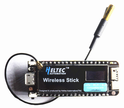
New features (based on below specs / source):

  • Apparently 800uA power consumption in sleep mode.
    (Disclaimer: this is my interpretation, formatting on page linked below is not clear about this.)
    A major improvement (while still 20+ times more than deep sleep current of ESP32)
  • 16 MB flash.
  • 0.49" OLED display. Yes that’s tiny!
    This will probably have 64x32 resolution.
  • New Wifi Antenna design (similar to TTGO Wifi LoRa32)
    (Finally an ESP32 LoRa board with a more properly placed Wifi antenna on top.)
  • ESP32, LoRa chip and display appear to be shielded with a metal cover (with cutout for display screen).

Source: https://www.aliexpress.com/item/Mini-ESP32-Wifi-Lora-Development-Board-with-0-49inch-oled-display-LoraBar/32960464571.html


Processor

Adopt Lexin’s ESP32 chip

  • 32-bit dual-core, 240MHz frequency
  • Integrated WiFi and Bluetooth
  • The main processor is completely free to run the user application.
  • An additional ULP coprocessor that monitors GPIOs, ADC channels,
    and controls most of the internal peripherals.

LoRa

Using Semtech’s SX1276 chip

  • Supports 433MHz, 470MHz, 868MHz, 915MHz quad-band optional
    Can be used as both a LoRa node and a micro gateway
  • Support LoRaWAN protocol
    Node transmission distance: up to 6KM in open space
  • Output power: up to +20dBm (±2dBm)

WiFi

  • 802.11 b/g/n/e/i
    802 802.11 n (2.4GHz), speed up to 150Mbps
    802 802.11 e: QoS mechanism to implement wireless multimedia technology
  • WMM-PS, UAPSD
  • MPDU and A-MSDU frame aggregation technology
    Block reply, fragmentation and reorganization
  • Beacon automatic monitoring / scanning
    802 802.11 i security features: pre-authentication and TSN
  • Support WPA / WPA2 / WPA2-Enterprise / WPS encryption
  • Infrastructure BSS Station Mode / SoftAP Mode
  • Wi-Fi Direct (P2P), P2P discovery, P2P GO mode and P2P power management
  • Support for IPv6

Bluetooth

Bluetooth v4.2 full standard, including traditional Bluetooth (BR/EDR)
and Bluetooth Low Energy (BLE)

  • Supports standard Class-1, Class-2 and Class-3 without external power amplifier
  • Enhanced precision power control
  • Output power up to +10 dBm
  • NZIF receiver with BLE reception sensitivity of -128 dBm
    Adaptive Frequency Hopping (AFH)Standard HCI based on SDIO / SPI / UART interface
    High speed UART HCI up to 4 Mbps
  • Support BT 4.2 controller and host protocol stack
  • Service Discovery Protocol (SDP)
    Universal Access Application (GAP)
  • Security Management Protocol (SMP)
  • Low power Bluetooth
    ATT ATT / GATT
  • HID
  • Supports all GATT-based Bluetooth low energy applications
  • SPP-Like Low-Power Bluetooth Data Transmission Protocol
    BLE BLE Beacon
  • A2DP / AVRCP / SPP, HSP / HFP, RFCOMM
  • CVSD and SBC audio codec algorithms
    Bluetooth piconet (Piconet) and scatternet (Scatternet)

Human interaction

  • 0.49 inch OLED screen
  • button (reset and program)

power supply

  • Input power: USB, lithium battery
  • Output power: +5V (only when USB is powered), +3.3V
    Integrated lithium battery charging circuit
  • External power supply controlled by IO port to facilitate development board to enter low power consumption

interface

  • UART UART, SPI, I2C, I2S, Mirco SD card
  • 12 - bits ADC, 8 - bits DAC
  • 29 general GPIO ports

storage

  • FLASH: 64Mb (16MB)

Power consumption

  • Sleep current: 800uA

Mechanical structure

  • Size: 60mmX23mmX8mm
2 Likes

I checked the pin wirings for the new TTGO T-Fox and found these:

#define HAS_LED NOT_A_PIN // green on board LED is useless, because it's wired to GPIO25 = LORA_RST

//#define LED_ACTIVE_LOW 1 // Onboard LED is active when pin is LOW
#define HAS_BATTERY_PROBE ADC1_GPIO35_CHANNEL
#define BATT_FACTOR 2 // voltage divider 100k/100k on board
#define HAS_BUTTON GPIO_NUM_36 // on board button (next to reset)

// Pins for I2C interface of OLED Display
#define MY_OLED_SDA (21)
#define MY_OLED_SCL (22)
#define MY_OLED_RST U8X8_PIN_NONE

// Pins for on board DS3231 RTC chip
#define HAS_RTC MY_OLED_SDA, MY_OLED_SCL // SDA, SCL

// Pins for LORA chip SPI interface, reset line and interrupt lines
#define LORA_SCK (5)
#define LORA_CS (18)
#define LORA_MISO (19)
#define LORA_MOSI (27)
#define LORA_RST (25)
#define LORA_IRQ (26)
#define LORA_IO1 (33)
#define LORA_IO2 (32)

That means:

  1. Unfortunately the green on board LED is useless, because it seems wired to RESET line of LORA module.
  2. The description in https://nl.aliexpress.com/item/TTGO-T-Vos-LoRa32-V1-1-433-868-915-mhz-ESP32-LoRa-OLED-0-96-inch/32951759794.html seems to be erraneous, since it says LORA RESET is GPIO23, but on my module it is GPIO25.
1 Like

TTGO T-Fox running new paxcounter v1.7.12 which supports on board RTC chip Maxim DS3231 to keep time:

IMG_20190120_130752

2 Likes

I found some additional details on my TTGO T-Fox board:

  • Powerswitch: GPIO25 controls a MOS-FET which switches power supply for LoRa-Chip (HPD13) and display. So for low power applications these components can be powered off and on by software.

  • This does not apply to the USB-UART chip (CP2104), it’s always powered and the suspend inputs are not wired to the CPU

  • LoRa-chip for the “27dBm” version is a HPD13AP, powered with 5V.

  • There is a solder bridge on the board to select power of LoRa chip: 3,3V or 5V

  • RTC chip DS3231 interrupt output line is wired to GPIO34, so can be used to wake up ESP32 from deep sleep by an alarm generated by the RTC chip.

  • RTC is powered with 3,3V when board runs on USB or battery power, and is powered by backup battery when board power goes off.

  • Battery power can be measured via a voltage divider (100k/100k) wired to GPIO35

  • The on board LED is connected to the power switching line and has active low logic, so is more or less useless (light on = power off / light off = power on)

So the T-Fox brings some new features to implement low power applications.

1 Like

First, thank you all for those threads, they really help me out using those boards.

Can you check if the CP2104 is also powered (not suspended) when running on 3.3V from a LiPo?
I read somewhere, that the CP2104 in contrast to the CP2102 suspends when not being connected to D+/D-.
Ideally, could you check the power consumption in deep sleep?

A nice start but a missed opportunity if the UART and voltage divider cannot be switched off.
The UART chip and voltage divider probably draw (much) more current than the display in sleep and HPD13 in sleep/standby mode. The voltage divider alone at 3.7V draws 18.5 uA already.

Can you provide a sample code to run for deep sleep operation?

As far as i overlook it, the following components will contiously draw battery power, and cannot be controlled by software on ESP32:

  • RTC (DS3221)
  • Voltage Divider for battery monitoring (2x 100k)
  • 3,3V LDO (ME6211)
  • USB/UART (CP2104), if it does not suspend autonomous

Hello guys,

I made a small pcb to avoid the power consumption of my heltec v1. I used an attiny85 to control the power ON and OFF of my board, this way I achieved around 20uA in sleep mode (the deep sleep mode consumption from attiny).

Just using some transistor and the attiny85.

I hope it can helps someone =D

1 Like

Prototype code (for TTGO LoRa v1) is available on GitHub: https://github.com/Nature40/Satellite-BatCave

maybe … if you have a link ? :wink:

Battery control circuit:

Just replace the BC448 for one C32740
image

Attiny85 Code:

#include <avr/sleep.h>
#include <avr/wdt.h>

#ifndef cbi
#define cbi(sfr, bit) (_SFR_BYTE(sfr) &= ~_BV(bit))
#endif
#ifndef sbi
#define sbi(sfr, bit) (_SFR_BYTE(sfr) |= _BV(bit))
#endif

int pinLed = 3;
volatile boolean f_wdt = 1;

void setup(){
  pinMode(pinLed,OUTPUT);
 // approximately 4 seconds sleep
  //setup_watchdog(8);
}

void loop(){
  if (f_wdt==1) {  // wait for timed out watchdog / flag is set when a watchdog timeout occurs
    f_wdt=0;       // reset flag

    digitalWrite(pinLed,HIGH);  // let led blink
    delay(2000);
    digitalWrite(pinLed,LOW);

    pinMode(pinLed,INPUT); // set all used port to intput to save power

    // Parameter should be multiple of 8 and should be grater than 8 
     sleep_tiny(8);
    //sleep_tiny_750();
    
    pinMode(pinLed,OUTPUT); // set all ports into state before sleep
  }
}

// set system into the sleep state 
// system wakes up when wtchdog is timed out
void system_sleep() {
  cbi(ADCSRA,ADEN);                    // switch Analog to Digitalconverter OFF
 // setup_watchdog(8);;
  set_sleep_mode(SLEEP_MODE_PWR_DOWN); // sleep mode is set here
  sleep_enable();
  sleep_mode();                        // System sleeps here
  sleep_disable();                     // System continues execution here when watchdog timed out 
  sbi(ADCSRA,ADEN);                    // switch Analog to Digitalconverter ON
}

// 0=16ms, 1=32ms,2=64ms,3=128ms,4=250ms,5=500ms
// 6=1 sec,7=2 sec, 8=4 sec, 9= 8sec
void setup_watchdog(int ii) {

  byte bb;
  int ww;
  if (ii > 9 ) ii=9;
  bb=ii & 7;
  if (ii > 7) bb|= (1<<5);
  bb|= (1<<WDCE);
  ww=bb;

  MCUSR &= ~(1<<WDRF);
  // start timed sequence
  WDTCR |= (1<<WDCE) | (1<<WDE);
  // set new watchdog timeout value
  WDTCR = bb;
  WDTCR |= _BV(WDIE);
}
  
// Watchdog Interrupt Service / is executed when watchdog timed out
ISR(WDT_vect) {
  f_wdt=1;  // set global flag
}

void sleep_tiny (int seconds){

  int m = 8;
  int t = seconds/m;
  for (int i=0;i<t;i++){
    setup_watchdog(m);
    system_sleep();
  }
  
}


void sleep_tiny_750 (){
  
  for (int i=4;i<6;i++){
    setup_watchdog(i);
    system_sleep();
  }

If you need anything else let me know!

1 Like

Guys,

I really need a help with my esp heltec board. I have two main problems

1 - My receive node stops to work after a few minutes. I’m using LoRa.parsePacket();
2 - If I increase the message size ( like 15 bytes) it stops to receive, when I increase the message the receiver stops to work more often too.

Please can anyone help me with this? Im blocked for weeks. =/

Without link to the code running on your Heltec board there won’t be any answers possible here.

Hello Verkehrsrot,

Even with the OLED_LoRa_Receiver and OLED_LoRa_Sender examples I’m having this kind of problem.
Problem 1:
My receive just stops to receive, it’snt blocked, but LoRa.parsePacket() just return zero after a while, when a reset the module it start to receive again.
Problem 2:
For the size of the packet how many bytes is the maximum? I saw in the datasheet of SX1276 that we could send a packet with 256 bytes but Im not even close and the receive start to lose a lot of packages when the package has a size like 15 bytes.

Dou you guys think that it could be my board? How many bytes did u send whitout a considerable packet loss.