depends which oled… if its small and based on SSD1306 … yes, it worked for me
White 4Pin 0.66" OLED Display Screen IIC I2C SSD1306 64x48 for Adurino AVR STM32
see GitHub - greiman/SSD1306Ascii: Text only Arduino Library for SSD1306 OLED displays
depends which oled… if its small and based on SSD1306 … yes, it worked for me
White 4Pin 0.66" OLED Display Screen IIC I2C SSD1306 64x48 for Adurino AVR STM32
see GitHub - greiman/SSD1306Ascii: Text only Arduino Library for SSD1306 OLED displays
Tip: When use of text is sufficient and true graphics operations are not needed:
U8x8 (part of the U8g2 library) uses less memory and has smaller footprint than U8g2.
Note: U8x8 also supports multiple fonts and custom definable characters, but these features will also increase memory usage.
Most fonts are available in different versions. For minimal memory usage select the font version with smallest size (size versus characters/symbols supported in the font).
Any idea how to upload anything to LoRa32u4 from windows arduino IDE ?¿
Already installed drivers.
Already assigned same com port to regular and bootloader.
Need help, thanks.
Please give more details.
What are you trying to do?
What is not working?
What happens?
What drivers are you referring to, USB COM port drivers?
What board have you selected in Arduino IDE?
Sometimes/often you may have to press the reset button just before uploading sketch.
ATmega28u4 USB switches port between 2 different COM port numbers, one after reset for bootloader and one for normal operation. Switching and having the operating system recognize the COM port switch takes some time (seconds).
How / On which OS?
Could this be the reason for why your upload is not working?
Hi all,
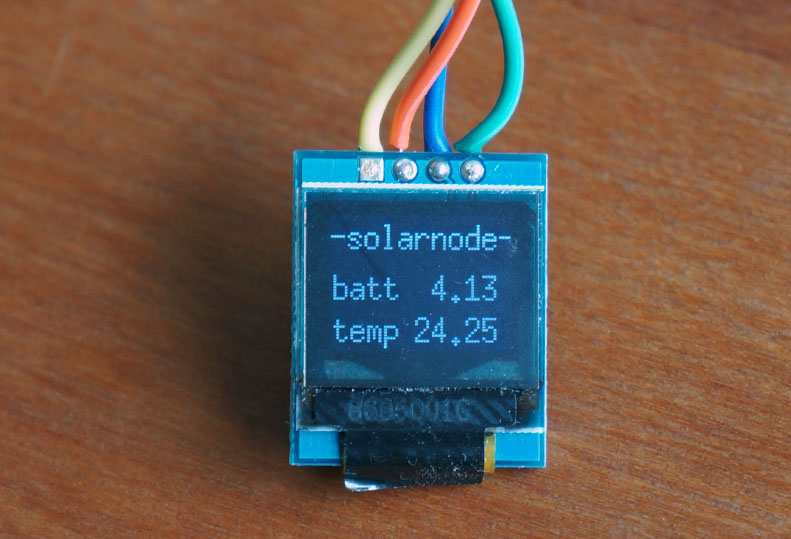
We have been using this module for over a year now, in different applications and with different sensors. I love this board!
To compensate for small memory, we do use a miniaturized version of LMIC, gps and such. ABP is used for simplicity, and also this means we do not have to solder in the extra wire.
Shared code needs to be made nicer for re-use. The github provides older variations with more function. Our intention is to make this code easier to use for all, so suggestions are welcome.
![]()
![]()
![]()
![]() well done !
well done !
I am waiting for it… I am doing some tests but this is not working for me with Wire library…
I’am trying to minimize the sleep current on a lora32u4 . Several posts hint to the voltage regulator as a source of current consumption. According to the documentation the voltage regulator can be disabled by connecting the EN pin to the ground. It looks however that this cuts off power to the processor, am i rigth ? Would it be possible to power the board then by connecting a lipo directly to the 3.3V pin ? If not what is the reason of being able to disable to voltage regulator ?
> According to the documentation the voltage regulator can be disabled by connecting the EN pin to the ground. It looks however that this cuts off power to the processor, am i rigth ?
Correct, at least thats the case for the Adafruit boards, yours could be different I guess.
> Would it be possible to power the board then by connecting a lipo directly to the 3.3V pin ?
If you try that you stand a very good chance of destroying the board, LoRa device etc. A LiPo could be up to 4.2V, not a good idea to connect one to a 3.3V circuit.
> If not what is the reason of being able to disable to voltage regulator ?
So that something external can turn of the 3.3V output of the regulator, and hence also the components connected to it.
On some other boards the voltage regulator can be disabled as a feature implemented by design (by solder jumper or external pin) to prevent it drawing quiescent current when the board is externally powered with 3.3V.
Disabling the regulator apparently also prevents it drawing quiescent current.
If this works the same for all regulators with EN pin I don’t know but it’s possible to give it a try.
(I’m not sure if all regulators can handle 3.3V external input on their output pin when they are disabled.)
Another part that will probably negatively impact sleep current of the board is the battery charger chip.
If you want to power the board by battery directly on the 3.3V pin without quiescent current losses from a voltage regulator then it’s possible to use LiFePO4 (lithium ion phosphate) cells which have a nominal voltage of 3.2V. (Be aware that these cells usually don’t have an overdischarge protection built in.)
When powering a simple board externally with 3.3V (e.g. Arduino Pro Mini) it often helps to remove the voltage regulator from the board to minimize sleep current. For more advanced boards that include a battery charger removing only the voltage regulator will be much less effective (and more difficult because of many smaller SMD parts).
Please precise which board version you are using!
On v1.2, I had my best low power result using 5v (neither Batt, nor 3.3v) pin.
I’am using the Lora32u4 II by BSfrance wich is marked with V1.2 near the usb port so thats probably the same board.
Hi everyone,
i trying to get a bs france Lora32u4 II board to run. Board version is 1.3(!) and it seems to be different than the 1.2.
First of all, i’m not sure which version i got. I want 866Mhz.
On the back there are two white boxes, one saying 866MHz and one 915MHz but there is no mark which one it is.
Even more confusing, after uploading an example Sketch, in the arduino IDE it says: “Port /dev/ttyACM1 Lora32u4 (433MHz)”
I followed as far as possibe those instructions: https://www.youtube.com/watch?v=0dfMrWHWmqw but i didn’t solder anything because there is only one solder pad on the back instead of three.
So my question is how can i find out which frequency is used. and second how can i see if the connection to the gateway is working? The next gateway is around 1.5 kilometers away. Is it possible with this board?
Thanks in advance
Forget to mention: Of course i selected the 866-915MHz version in the Board selection.
Read the extensive information in this thread first before asking other forum users for help.
This thread is not intended for providing help for instructions in other people’s Youtube videos!
Both V1.2 and V1.3 are clearly described in this thread, including their differences and instructions how to get the board up and running.
If you do not want to solder DIO1 then you might try example ttn-abp.ino to use ABP.
That should probably work without DIO1 connected, ttn-otaa.ino will not work without DIO1 connected.
For normal (OTAA) operation you will have to connect/solder DIO1 anyway.
If the board says 868/915 MHz then it probably is.
It is possible (but less likely) that a 433MHz LoRa module is mounted on the board.
I find it unlikely though that the Arduino IDE would be checking whether the module is a 868/915 or 433MHz version. The 433MHz message may possibly be incorrect (caused by USB driver).
I have no experience with Arduino on Linux or OSX, but when I connect my LoRa32u4 V1.2 to a Raspberry Pi then lsusb shows it as ID 239a:800c without LoRa32u4 and without frequency. This may be different for V1.3 though (I have none to test it).
Thx for your reply.
I got it to work after some time. On the first post, i didn’t see any information about v1.3 so i thought there is no.
There are not many guides how to get startet with this board so i reffered to the one on youtube to make clear what i’ve already done.
DIO1 is connected by default in v1.3 so its not neccessary to do anything here.
lsusb shows 230a:800c in programming (boot) mode and 239a:800c during normal operation.
Additionally i had an error from the IDE because of a missing hex file. Was just a typo of Lora and lora so i need to rename the file.
Last it seemed as if the device could not register to the network. I got this message for i guess 30minutes
8715102: EV_TXSTART
9108467: Unknown event: 20
then it finally starts sending. Wohooo \o/
Good to hear that you got it working. ![]()
Ah yes, of course.
I already wrote the following before: ![]()
I have updated the topic start and added information for:
LMIC_setClockError()).
How about this “miniaturized version” of LMIC that was presented in this topic?
Based on the repository URL in the post you referenced:
The provided lmic_slim library:
It got an impression that it might be based on TinyLoRa but I don’t know (I have no experience with TinyLoRa).