Hi,
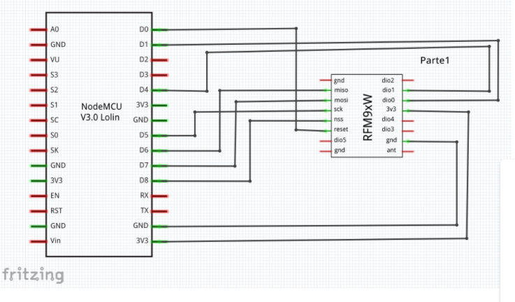
I’m a beginner at Lora. I got started by using the LMIC library and RFM95 module for testing. I changed some necessary parameters that are respective to my project ( include TTN information like DevEUI, APPEUI, APPKEY, and pins adjustment of NSS,…). I followed the connecting diagram as the image below. The problem came when uploading code for ESP, It continued showing up a window alarming that: warning: espcomm_sync failed An error occurred while uploading the sketch error: espcomm_open failed error: espcomm_upload_mem failed
I tried uploading without connecting to the Lora module and It was successful but when I reconnected it, It failed with an error was: ets Jan 8 2013,rst cause:4, boot mode:(1,4)
wdt reset
I really have no idea what the reason was. What should I do with this problem? Anyhelp would be appreciated.
Might want to take another look: D4 is not being used for SPI in the asker’s diagram, but rather as a generic GPIO to interface one of the DIO status pins of the radio.
And anyway, even unworkable pin choices wouldn’t prevent downloading or boot, but only lead to problems with subsequent operation.
Only things that caused issues for power, boot state, or serial communication would cause the reported problem. It’s not evident any of the shown connections should. Edit: comparison with the ESP8266 docs would suggest that “D4” is one of these pins.
Try disconnecting each pin one by one and check when you can upload code again. Try erasing flash as well. I would start with disconnection D0 and D4. I had trouble using D4 since it needs to be in a certain state when booting.
Thanks for all your help. I tried releasing D0 and D4 pin when uploading and it worked. It seems to be caused by the need for a certain state of D0 and D4 pin like above answer. However, when i reconnected these two pins after uploading, it came with another error shown on monitor was:
ets Jan 8 2013,rst cause:4, boot mode:(3,6)
wdt reset
*load 0x4010f000, len 1384, room 16 * tail 8 chksum 0x2d csum 0x2d v951aeffa ~ld Starting
*FAILURE * C:\Users\Admin\Documents\Arduino\libraries\MCCI_LoRaWAN_LMIC_library\src\lmic\oslmic.c:53
What does this error mean? How can i fix it? Thanks in advance.
Maybe you’re right. Forget to tell that I also encountered this warning: #pragma message(“Board not supported – use an explicit pinmap”)
when attempting to compile. I think it doesn’t matter so I just ignore it and upload. Then, it failed as you see.
You should see the ESP8266 documentation on boot mode pins.
You’ll unfortunately then have to translate that through the Arduino pin scheme (which if I recall might have similar nomenclature but mismatch what’s printed on the board silkscreen, as the board isn’t designed for Arduino).
Then pick you DIO pins from whatever pins do not have a role in determining boot mode. As far as LMiC is concerned these can be any available pins, as long as the software selection and wiring match. As far as the ESP8266 is concerned, they need to be pin usages (or at least levels - but how would you ensure that - the ESP8266 could reset while the radio retains state) which do not cause the wrong boot mode…