Hi Grant, i would like to be able to do the same with my mdot box, can you tell me if you achieve to configure the device?
I still haven’t been able to get it to work.
Hi Grant,
I got mine up and running just recently. I misled you with the AT commands - those are for the generic MDOT AT command firmware. Some of them work, but a quick look with the HELP command when connected to the MDOTBOX shows they are device specific. There is no join command.
Your configuration as shown from AT&V looks correct. I would do an AT&F to wipe it and start again. Minimum configuration for an OTA device seems to be:
AT+PN=1
AT+NI=0,
AT+NK=0,
AT+NJM=1
AT&W
AT+EXIT
Have a look at the console after doing exit and see what you can find. I hadn’t configured public mode, so was never getting an ACK.
It may be related to your regulatory location (AUS), perhaps the firmware isn’t as well tested on that. Also check you’re on v2.1.2 ftp://ftp.multitech.com/wireless/mtdot/
Firmware: 2.1.2
Library : 2.0.16-mbed126
Let me know how you get on.
Ben
2 Likes
Hi Ben,
I switched over from ABP to OTA and got it working. I used the help function on the mDot Box to map the fields. I used the following fields:
AT&F Reset Factory Defaults
AT+FSB=2 Frequency Sub-band
AT+PN=1 Public Network Enable/disable public network mode.
AT+NJM=1 Network Join Mode 0: Manual configuration, 1: OTA Network Join (default: 1)
AT+DI=devEUI Device ID Device EUI-64 (MSB) (8 bytes)
AT+NA=devAddr Network Address Network address (devAddr in TTN) (4 bytes)
AT+NK=0,App Key Network Key Configured network key (App Key in TTN) (16 bytes)
AT+NI=0,App EUI Network ID Configured Network EUI (App EUI in TTN) (8 bytes)
AT&W Save Configuration
The mDot Box now joins the network and I’m getting data through in Survey mode, but not Demo mode. What result did you get get?
Grant
1 Like
How did you fix this? I was having a similar issue, but mine is due to the Device ID resetting itself after the device is powered off.
EDIT: I did some research and found the DevEUI on the mDot Box is coded at the factory and not meant/able to be changed. In the end I updated my Device EUI in my TTN App to match the factory set DevEUI on the mDot Box. Joins are now successful after cycling the power on the mDot Box.
1 Like
Great news Grant
How are you intepreting the data from the mdot box? Got any suggestions how to plot this?
Trivia:
After losing several mdots to flash corruption I received some advice from @andrewl and Multitech. It involved rebooting into the bootloader and erasing the flash. This also erased the DevEUI so a special firmware to set the DevEUI was supplied. You could override the DevEUI here, but given that the DevEUI is printed on the sticker I’d seriously avoid changing it, and as you’ve done, fix the app. I’m also wondering how they knew the frequency without me specifying so perhaps it’s dictated by the DevEUI.
the firmware image you used to reset the Dev EUI is frequency specific, so presumably you used the 868MHz specific version without even knowing it!
Hey Brandon Did you work out this problem - this same has happen to me. Toggle the pn 1 - 0 and it connected. never to happen again.
I just made my configure script always toggle it back and fourth. I never saw it happen again but the toggling seems to work, so I just left it as is to prevent it happening again.
Thanks for your reply mate.
P
Is there a way to change the frequency band from US915 to AU915 with the AT commands for the mdot-box ?, is the problem that I am having since my Conduit gateway is configured for AU915
You need to load the AU firmware to the mDot box to adjust the sub-band settings.
Dear daforg, Did yourmDot box work with this change? Do you have a link where I can find it? Thanks in advance
I got the files from the local supplier I bought the hardware from (after I requested it). I’ve messaged you my email address, I can send you the files.
To change frequencies on an mDot Box (or a regular mDot) to AU915,
Install this firmware http://multitech.net/downloads/mdot-firmware-no-cmd-interface-switch-to-AU915.bin. Wait a few seconds for the device to boot and the firmware to do its magic.
Then install whatever firmware you like, provided it’s based on libmDot 2.0 or later.
I’m having trouble getting this working… I have the config below:
AT&V
Firmware: 2.1.2
Library : 2.0.16-mbed126
Device ID: 00:80:00:00:00:XX:XX:XX
Frequency Band: US915
Frequency Sub Band: 2
Public Network: on
Network Address: 00000000
Network ID: 70:b3:d5:7e:d0:XX:XX:XX
Network ID Passphrase:
Network Key: ce.d8.c1.a8.5c.6e.59.25.f6.72.e5.4c.XX.XX.XX.XX
Network Key Passphrase: 70B3D57ED0XXXXXX
Network Session Key: 00.00.00.00.00.00.00.00.00.00.00.00.00.00.00.00
Data Session Key: 00.00.00.00.00.00.00.00.00.00.00.00.00.00.00.00
Network Join Mode: OTA
Tx Data Rate: DR0
Tx Power: 20
Log Level: 6
Maximum Size: 242
Minimum Size: 11
Maximum Power: 20
Minimum Power: 2
Data: 0
OK
I’m not sure where (or how to generate) the key needed for the “AT+NK=” setting. Any pointers?
This is available from your TTN console when you register the device using ABP.
I’ve tried all of these… Do I need to format the string a certain way or something? 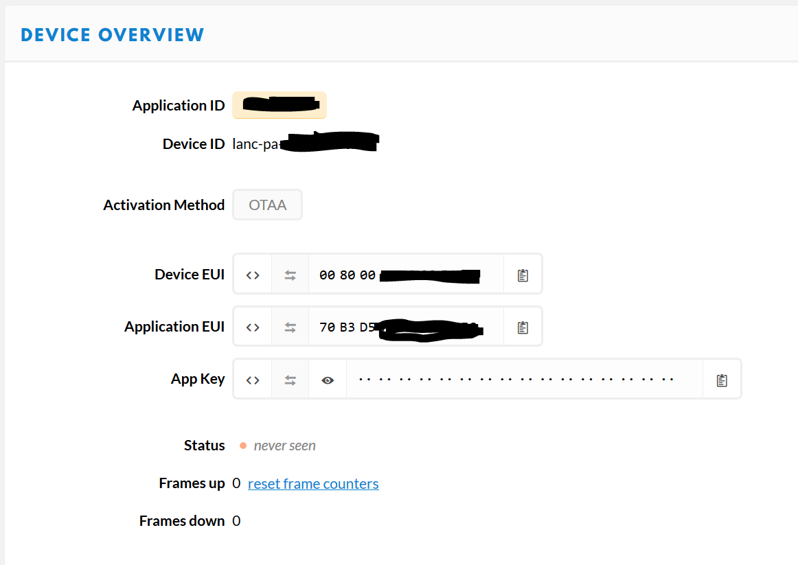
Thanks greatly, everyone, for sharing your work on the mDot Box and TTN.
I was able to connect to TTN easily following the clues here. I used the following:
at&f
at+fsb=2
at+pn=1
at+njm=1
at+nk=0,7B1964C03064F3795E4243XXXXXXXXXX
at+ni=0,70B3D5XXXXXXXXXX
at&w
Where:
nk is your TTN App Key
ni is your TTN Application EUI
These are both formatted in standard hex, just as they appear at the bottom of your device overview page under “example code”.
Note that the Device ID is pre-set at factory, no need to adjust that.
My config looks like this, then:
at&v
Firmware:               2.1.2
Library :               2.0.16-mbed126
Device ID:              00:80:00:00:00:xx:xx:xx
Frequency Band:         US915
Frequency Sub Band:     2
Public Network:         on
Network Address:        00000000
Network ID:             70:b3:d5:xx:xx:xx:xx:xx
Network ID Passphrase:
Network Key:            7b.19.64.c0.30.64.f3.79.5e.42.43.xx.xx.xx.xx.xx
Network Key Passphrase:
Network Session Key:    00.00.00.00.00.00.00.00.00.00.00.00.00.00.00.00
Data Session Key:       00.00.00.00.00.00.00.00.00.00.00.00.00.00.00.00
Network Join Mode:      OTA
Tx Data Rate:           DR0
Tx Power:               20
Log Level:              6
Maximum Size:           242
Minimum Size:           11
Maximum Power:          20
Minimum Power:          2
Data:                   0

OK
Now I just need to see if I can get the data to come up in survey mode. right now, my payload is incomprehensible.
I would love to get this to send GPS data to TTN, and then use it with TTN Mapper.
2 Likes
I asked about data format over on slack, and got an answer. Here’s the application payload format to decode temperature, lat and long at TTN:
function Decoder(bytes, port) {
 // Decode an uplink message from a buffer
 // (array) of bytes to an object of fields.

/*
Datenformat für Modus Survey GPS

Byte 0 is 0
Byte 1 is temperature in Celsius
Byte 2 is 0
Byte 3-6 is GPS Latitude
Byte 7-10 is GPS Longitude
Bytes 10+ is padding with 0
*/

 var boardtemp = bytes[1];
 var lat = ((bytes[3] << 24) | (bytes[4] << 16) | (bytes[5] << 8 ) | bytes[6])  / 2147483648*90; // 2^31 * 90
 var long = ((bytes[7] << 24) | (bytes[8] << 16) | (bytes[9] << 8 ) | bytes[10]) / 2147483648*180; // 2^31 * 180

  boardtemp = 1.8 * boardtemp + 32; //

 // if (port === 1) decoded.led = bytes[0];

return {
   boardtemp: boardtemp,
   lat: lat,
   long: long,
   };
}
There is also a TTN application that will read your box and post to ttn mapper @Verkehrsrot can help with that.
4 Likes