hi scl, yes I do, this one is the one from the receiver
Configuring LoRa module...
Setting device in lora modulation: ok
Setting frequency: ok
Setting power: ok
Setting sf: ok
Setting afcbw: ok
Setting rxbw: ok
Setting fdev: ok
Setting prlen: ok
Setting crc: ok
Setting cr: ok
Setting sync: ok
Setting bw: ok
Setting wdt: ok
Setting IQ inversion: ok
LoRa module ready.
Node 02010103: Receiving...
-1
4294967245
LoRa status:
Node 02010103: Receiving...
-1
4294967245
LoRa status:
Node 02010103: Receiving...
-1
4294967245
LoRa status:
Node 02010103: Receiving...
-1
4294967245
LoRa status:
Node 02010103: Receiving...
The 4294967245 is the answer to mac pause command
on the TX It looks like
Configuring LoRa module...
Setting device in lora modulation: ok
Stting frequency: ok
Setting power: ok
Setting sf: ok
Setting afcbw: ok
Setting rxbw: ok
Setting fdev: ok
Setting prlen: ok
Setting crc: ok
Setting cr: ok
Setting sync: ok
Setting bw: ok
Setting IQ inversion: ok
Setting wdt: ok
LoRa module ready.
Node 02010103:Sending...
Node 02010103 sending: HI
Pausing mac: 4294967245
sending to radio: HI
LoRa status:
Node 02010103:Sending...
Node 02010103 sending: HI
Pausing mac: ok
radio_tx_ok
4294967245
sending to radio: HI
LoRa status:
Serial1.write(“mac pause\r\n”);
//setting window to zero
Serial1.write(“radio set wdt 0\r\n”);
//setting the rx to continous mode of reception
Serial1.write(“radio rx 0\r\n”);
Serial.println(Serial1.read());
the sender looks like
Serial.print("Pausing mac: ");
Serial1.write(“mac pause\r\n”);
delay(50);
while (Serial1.available()) Serial.write(Serial1.read());
Serial.print("sending to radio: ");
Serial1.write(“radio tx 1\r\n”);
while (Serial1.available()) Serial.write(Serial1.read());
Try setting the radio parameters just after mac pause, the LoRaWAN protocol might be adjusting the parameters. So in between of mac pause and radio rx 0.
After sending the rx command RN2483 will first transmit ok and then when it receives something radio_rx <data>. So you just have to wait then with serial.available().
What is this 52 number? Is this the length of the received packet? Try printing the received message.
Do you use the readWaitLn function, this doesn’t work without timeout very well…
The busy keyword means the module is actually listening. So when it has received something this should disappear. Busy is correct is what I mean to say.
Now try to send some message. First with radio set iqi on and the radio set iqi off. And make sure the parameters are the same, also in the transmitter. In one of your previous messages I saw you are pausing mac just before sending, try setting radio parameters after pausing in the transmitter as well. Otherwise I will quicly run out of ideas as well.
OK then it is waiting to get something, however I am sending and it does not receive anything yet. Now I have both devices with radio set iqi on and it seems not working, the say way i had them before with off…
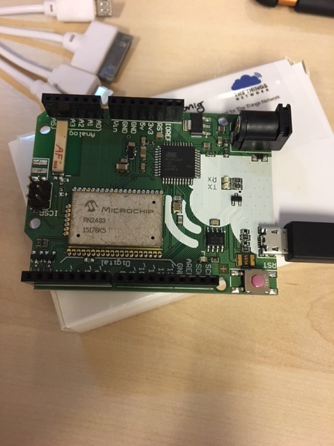
A picture in which sense? I don’t have anything connected to thet board.
Just a photograph of the two RN2483 modules and how they are connected.
From the code I cannot make up why it doesn’t work, perhaps the phyical setup is wrong.
Otherwise I don’t know it. I was able to communicate between my RN2483 module and a SX1276 module, so it should be possible to send and receive p2p.
Are you able to communicate with a gateway? Perhaps you can use the other module to eavesdrop on this connection.
I don’t have anything connected to it, they were able to connect to the gateway indeed, but I only have two modules, so it would not be enough, further, if I disable the LoRaWan stack, the gateway won’t see much right?
@scl how does your code look like? I mean the sending and receiving part
My set up in both nodes is this
 Serial.print("Pausing mac: ");
  Serial1.write("mac pause\r\n");
  delay(50);
  while (Serial1.available()) Serial.write(Serial1.read());

  Serial.print("Setting device in lora modulation: ");
  Serial1.write("radio set mod lora\r\n");
  delay(50);
  while (Serial1.available()) Serial.write(Serial1.read());
  LoRaBlink();
  Serial.print("Setting frequency: ");
  Serial1.write("radio set freq 868000000\r\n");
  delay(50);
  while (Serial1.available()) Serial.write(Serial1.read());
  LoRaBlink();
  Serial.print("Setting power: ");
  Serial1.write("radio set pwr 14\r\n");
  delay(50);
  while (Serial1.available()) Serial.write(Serial1.read());
  LoRaBlink();
  Serial.print("Setting sf: ");
  Serial1.write("radio set sf sf12\r\n");
  delay(50);
  while (Serial1.available()) Serial.write(Serial1.read());
  LoRaBlink();
  Serial.print("Setting afcbw: ");
  Serial1.write("radio set afcbw 125\r\n");
  delay(50);
  while (Serial1.available()) Serial.write(Serial1.read());
  LoRaBlink();
  Serial.print("Setting rxbw: ");
  Serial1.write("radio set rxbw 250\r\n");
  delay(50);
  while (Serial1.available()) Serial.write(Serial1.read());
  LoRaBlink();
  Serial.print("Setting fdev: ");
  Serial1.write("radio set fdev 5000\r\n");
  delay(50);
  while (Serial1.available()) Serial.write(Serial1.read());
  LoRaBlink();
  Serial.print("Setting prlen: ");
  Serial1.write("radio set prlen 8\r\n");
  delay(50);
  while (Serial1.available()) Serial.write(Serial1.read());
  LoRaBlink();
//  Serial.print("Setting crc: ");
//  Serial1.write("radio set crc on\r\n");
//  delay(50);
//  while (Serial1.available()) Serial.write(Serial1.read());
  LoRaBlink();
  Serial.print("Setting cr: ");
  Serial1.write("radio set cr 4/8\r\n");
  delay(50);
  while (Serial1.available()) Serial.write(Serial1.read());
  LoRaBlink();
  Serial.print("Setting sync: ");
  Serial1.write("radio set sync 12\r\n");
  delay(50);
  while (Serial1.available()) Serial.write(Serial1.read());
  LoRaBlink();
  Serial.print("Setting bw: ");
  Serial1.write("radio set bw 250\r\n");
  delay(50);
  while (Serial1.available()) Serial.write(Serial1.read());
  LoRaBlink();
  Serial.print("Setting wdt: ");
  Serial1.write("radio set wdt 0\r\n");
  delay(50);
  while (Serial1.available()) Serial.write(Serial1.read());
  LoRaBlink();
  Serial.print("Setting IQ inversion: ");
  Serial1.write("radio set iqi on\r\n");
  //Serial1.write("radio get iqi\r\n");
  delay(50);
  while (Serial1.available()) Serial.write(Serial1.read());
  LoRaBlink();
This was my code to control SX1276, in combination with the LMiC library and an XMC1100 starter kit. But the RN2483 should be able to do the same with some commands (because under the hood it is the same).
I was using RN2483 with a USB-UART (3.3Volt) converter and a serial console. And entering commands manually. Shouldn’t you use an antenna btw, i see none in your picture?
According to the doc of TTU it does not need an extra antenna, there’s one antenna the one labeled in the picture as AF.
Looking your code, I see two things different from mine, first you disable the CRC when transmitting is that a reason for? I have done it as well, no luck thouh. The second one is that you specify a payload of , where can I do that in the RN2483 ? with the command radio tx 5 and radio rx 5?
Shouldn’t make a difference, disabling CRC only you would get an error in receive if the CRC is incorrect but it would give a signal.
Payload length is only needed when using implicit header… So that one is not used. I did both receiving and transmitting with this code, but it seems I have mixed it up a bit.
I used this code below in the receive interrupt btw:
u1_t len = readReg(0x13);
u1_t snr = readReg(0x19);
u1_t rssi = readReg(0x1A);
u1_t buffe[512] = {0};

// set pointer to 0
writeReg(0x0D, 0x00);
readBuf(0x00, buffe, len);

writeReg(0x12, 0xFF);
But this has nothing to do with your problem. I think I don’t know how to solve your problem unfortunately, I ran out of ideas. The antenna seems te be fine.
Thank you very much for your help scle, I really appreciate it. I don’t know neither where is the issue, maybe I should throw away this platform and go for a different one. I am run out of ideas as well.
I have two nodes like this: 868MHz RN2483 LoRa™ Technology Mote and managed to get them to talk to each other as described in the link @sergiosena provided earlier (setting all parameters etc.).
I decided to take small steps and started with a simple setup connecting both nodes to my Windows PC. Both were recognised as serial ports (in my case COM6 & COM7). I then used a serial monitor/terminal application (like Tera Term) and initially entered all commands per hand. I know, not optimal but served the purpose and I know that the nodes can talk to each other.
Now my plan is to write scripts/programs to automate the stuff so thanks to all for some ideas in this thread.
Well my nodes are already mounted in the TTU, so as starting I am using arduino workbench to develop, the code, I had just to simple functions on configuing the other sending or receiving. Thus not big deal, I increased arduino void function timeout to have enough transmission time, but as you see in the post not luck…
how about running a simple “serial in, serial out sketch” on Arduino as described here for the WiFi chip: Arduino to ESP8266 By Serial Communication? I guess this way the RN2483 shall be easier to control during your tests.
Thanks @ksl2europe, but my chip is embbeded on the aurdion board, since is the The Things Uno, so you mean that I read from the serial pins of the TTU the serial port?
Interestingly, I also played with the P2P connection between two RN2483 . Indeed, it succeeds in transmitting data in both directions. Just fun to test,