I have built a LoraWan sensor that sends its data to TTN. The base is a LilyGo/TTGO. As sensor I use a BME280. The software is compiled with the Arduino IDE. The software is based on the library LMIC. When I turn on the sensor everything works fine and data is transmitted to TTN. I send one packet every 20 minutes.
Now I tried to run the node from battery. It works, but the battery runs out in a few days.
I then tried to use deep_sleep. However with moderate success. The node transmits as it should. The data also arrive at the Geteway. At TTN, however, data arrives only sporadically. Sometimes no data arrives for hours. Sometimes several packets in a row.
Has anyone had similar experiences and then found a solution? I would be pleased about feedback.
Eureka!
I have found the solution.
After waking up from deep sleep, the Sketch starts again at “void setup”. That means, the LMIC is initialized again by the command “os_init();”. But a multiple call of this function leads to problems. It seems that the LMIC remembers something from the initialization in spite of deep slepp. Now I immediately close the LMIC before the deep sleep starts, with the command “LMIC_shutdown ();”.Now everything works fine.
Yes, the XIAO SAMD21 is good for a simple TTN node.
There are two revised PCBs on the way, both have a FRAM, which is used to (successfully!) save session state, so a power down or reset does not resut in a fresh OTAA join.
Many thanks for the suggestions. First, I will now test my current configuration. The node will now be exposed to the winter weather.
For information: My node sends voltage, temperature, humidity and air pressure every 20 minutes. I do not use OTTA but ABP with Counter Check.
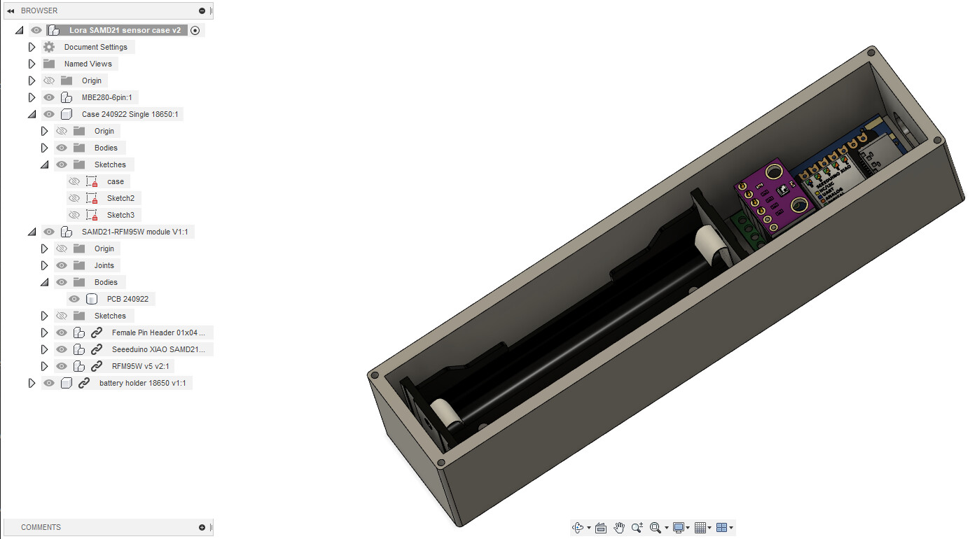
interesting. I just started designing a 3D printed enclosure, using your Dec 2022 design as a basis but I want it to be still usable with your revised design, if it has different size/location of mounting holes/location of connectors. If possible, I want to make my box parametric (or depending on the new layout, with multiple fixing options) so both PCBs can be accommodated
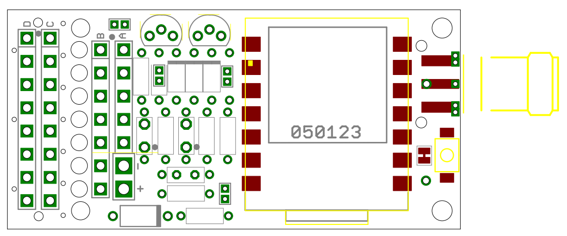
The smaller one, increased in length by 2mm to 41mm x 19mm, but does not have mount holes as such (no room) its more designed for use a tracker, covered in shrink film etc. Or as a pico balloon tracker, so has hanging holes. It changed size because the FRAM was so important in making a tiny deep sleep OTAA TTN node possible.
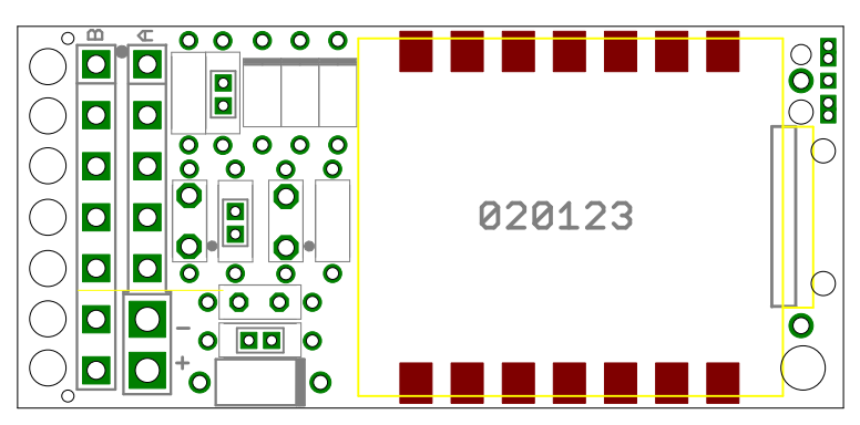
The ‘larger’ one does have mount holes and can be fitted with an edge SMA, so more useful for box mounting or general purpose TTN nodes. Still smallish though, 49.5mm x 24mm;
I’ve used the 240922 PCB. Almost done with the case, only need to do the lid. But I can in a minute start the printer to make a first test fit prototype. The 18650 holder is in NL, so that’s only something for Friday. It’s a trial anyway, I already see things I’ll change in a next revision.
I’m using meltable mounting posts, sort of a once-off mounting solution but if all is working before mounting it in, then there should be no need to take it out anymore. The USB port will still be reachable. I’ll make a stub to shut off the USB port, to keep creepy crawlers out and to make it a tiny bit splash proof.