From the datasheet it seems they are identical apart from the firmware version they run, but I was unable to find any info regarding each version’s compatibility with TTN.
I am sorry if this is a dumb question but does it make a difference which one I purchase? Any advice would be greatly appreciated. Thanks!
Thanks for your response @JDP ! I’ve ordered the chip already and will update when I finally get it (sometime in Feb because there is a serious shortage of chips nowadays).
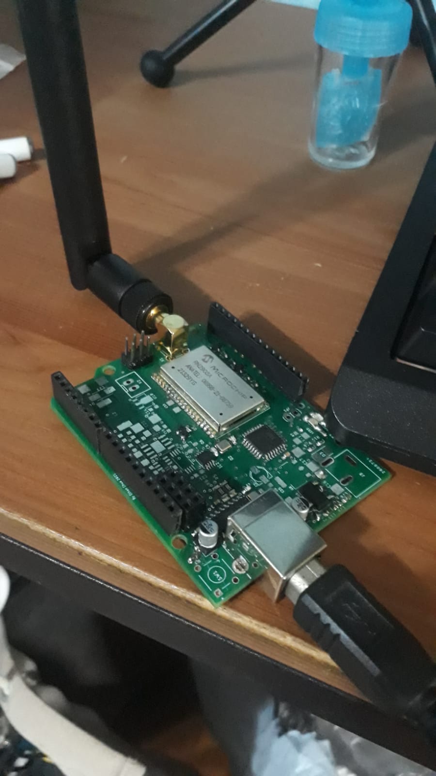
Hi, everyone finally got down to soldering everything onto the Arduino clone I designed:
Here is my result with using TheThingsNetwork Library:
Sketch:
#include <TheThingsNetwork.h>
#include <SoftwareSerial.h>

SoftwareSerial loraSerial(10, 11); // RX, TX

// Set your AppEUI and AppKey
const char *appEui = "appEUI";
const char *appKey = "secret appKey";

#define debugSerial Serial

// Replace REPLACE_ME with TTN_FP_EU868 or TTN_FP_US915
#define freqPlan TTN_FP_AS920_923

TheThingsNetwork ttn(loraSerial, debugSerial, freqPlan);

void setup()
{
  loraSerial.begin(9600);
  debugSerial.begin(9600);

  initialize_radio();

  debugSerial.println("-- STATUS");
  ttn.showStatus();

  debugSerial.println("-- JOIN");
  ttn.join(appEui, appKey);
}

void loop()
{
  debugSerial.println("-- LOOP");

  // Prepare payload of 1 byte to indicate LED status
  byte payload[1];
  payload[0] = (digitalRead(LED_BUILTIN) == HIGH) ? 1 : 0;

  // Send it off
  ttn.sendBytes(payload, sizeof(payload));

  delay(10000);
}
void initialize_radio()
{
  //reset rn2483
  pinMode(12, OUTPUT);
  digitalWrite(12, LOW);
  delay(500);
  digitalWrite(12, HIGH);

  delay(100); //wait for the RN2xx3's startup message
  loraSerial.flush();

  //Autobaud the rn2483 module to 9600. The default would otherwise be 57600.
  String response = "";

  // Try a maximum of 10 times with a 1 second delay
  for (uint8_t i=0; i<10 && response==""; i++)
  {
    delay(1000);
    loraSerial.write((byte)0x00);
    loraSerial.write(0x55);
    loraSerial.println();
    // we could use sendRawCommand(F("sys get ver")); here
    loraSerial.println(F("sys get ver"));
    response = loraSerial.readStringUntil('\n');
  }
}
The Serial monitor response:
-- STATUS
EUI: "myDevEUI"
Battery: 3184
AppEUI: "myAppEUI"
DevEUI: "my devEUI"
Data Rate: 0
RX Delay 1: 1000
RX Delay 2: 2000
-- JOIN
Model: RN2903
Version: 1.0.5
Sending: mac set deveui "myDevEUI"
Sending: mac set adr off
Sending: mac set deveui "myDevEUI"
Sending: mac set appeui "myAppEUI"
Sending: mac set appkey "myAppKey"
Sending: mac save
Sending: mac set adr off
Sending: mac set rx2 2 923200000
Response is not OK: invalid_param
Sending: mac set ch dcycle 0 799
Response is not OK: invalid_param
Sending: mac set ch dcycle 1 799
Response is not OK: invalid_param
Sending: mac set ch dcycle 2 799
Response is not OK: invalid_param
Sending: mac set ch freq 2 922000000
Response is not OK: invalid_param
Sending: mac set ch drrange 2 0 5
Response is not OK: invalid_param
Sending: mac set ch status 2 on
Sending: mac set ch dcycle 3 799
Response is not OK: invalid_param
Sending: mac set ch freq 3 922200000
Response is not OK: invalid_param
Sending: mac set ch drrange 3 0 5
Response is not OK: invalid_param
Sending: mac set ch status 3 on
Sending: mac set ch dcycle 4 799
Response is not OK: invalid_param
Sending: mac set ch freq 4 922400000
Response is not OK: invalid_param
Sending: mac set ch drrange 4 0 5
Response is not OK: invalid_param
Sending: mac set ch status 4 on
Sending: mac set ch dcycle 5 799
Response is not OK: invalid_param
Sending: mac set ch freq 5 922600000
Response is not OK: invalid_param
Sending: mac set ch drrange 5 0 5
Response is not OK: invalid_param
Sending: mac set ch status 5 on
Sending: mac set ch dcycle 6 799
Response is not OK: invalid_param
Sending: mac set ch freq 6 922800000
Response is not OK: invalid_param
Sending: mac set ch drrange 6 0 5
Response is not OK: invalid_param
Sending: mac set ch status 6 on
Sending: mac set ch dcycle 7 799
Response is not OK: invalid_param
Sending: mac set ch freq 7 923000000
Response is not OK: invalid_param
Sending: mac set ch drrange 7 0 5
Response is not OK: invalid_param
Sending: mac set ch status 7 on
Sending: mac set pwridx 1
Response is not OK: invalid_param
Sending: mac set retx 7
Sending: mac set dr 5
Response is not OK: invalid_param
Sending: mac join otaa
Join not accepted: denied
Check your coverage, keys and backend status.
Sending: mac join otaa
Join not accepted: denied
Check your coverage, keys and backend status.
Changing the #define freqPlan TTN_FP_AS920_923 to TTN_FP_US915 resolved all the invalid_param errors and so I am quite certain this means that this RN2903 board is “hard-coded” to the US915 frequency spec with no means of changing it?
Oh well just thought it would still be able to work with AS920-923…
If anyone has experience with using the RN2903, I would be most grateful to know if it is possible to change the frequency settings or is the board hard-coded to US-915MHz?
I just tried using updating the firmware using the Microchip LoRa Development Utility and the firmware here (DFU mode) but ended up bricking the RN2903. Did I choose the wrong firmware hex? Will solder wires to the ICSP pins, order and a PCIKIT3 and try the ICSP method.
Looks like that’s the right firmware. It is hard to totally brick a module, however you might need to switch to low level mode. (Sorry too long ago I used the utility to recall what it’s called)
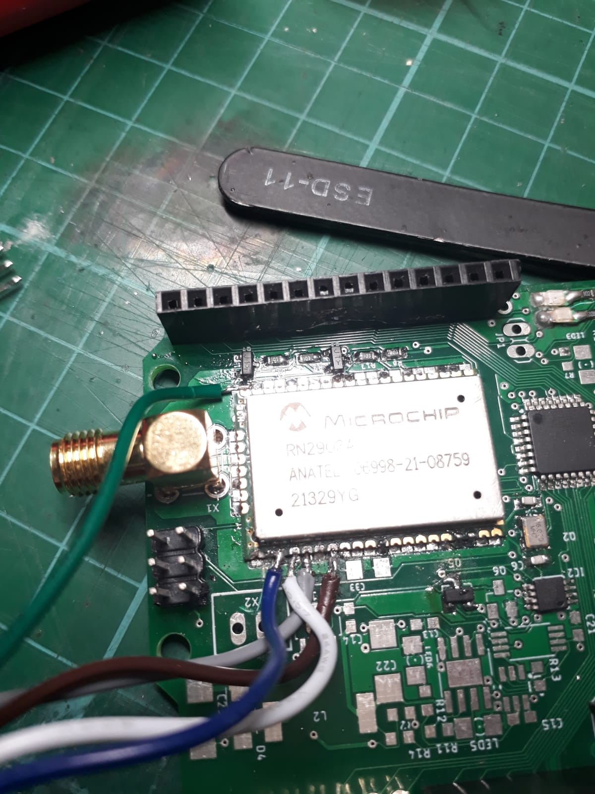
I recently got my PICV3 Kit from this link and soldered everything up according to the RN2903 datasheet as well as this guide.
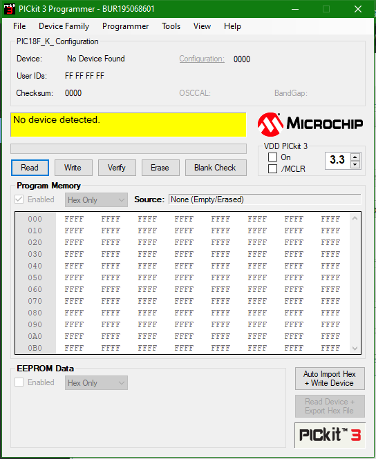
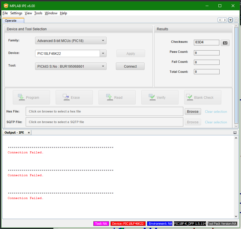
However very sadly it seems that the RN2903 chip is bricked beyond help as both the PICKit3 Utility as well as the MPLab X IPE could not connect to the board.
PICKitV3 utility:
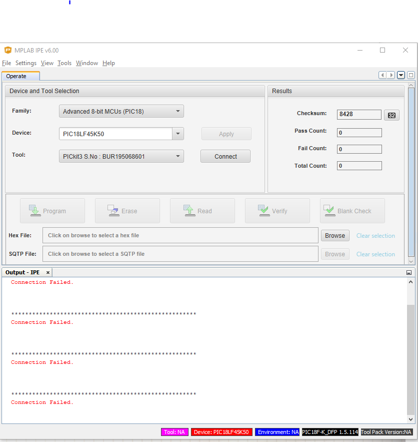
MPLabXIPE:
Tried both LF45K50 and LF46K22 but to no avail.
Perhaps I will order the different model next time and design a PCB with proper ICSP breakout headers so I can eliminate the potential errors in soldering but I checked the connections with a multimeter several times and there was continuity…
Oh well for now I will just chuck this RN2903 aside in favour of a RAK3172…
Thanks regardless for all those who have helped me!