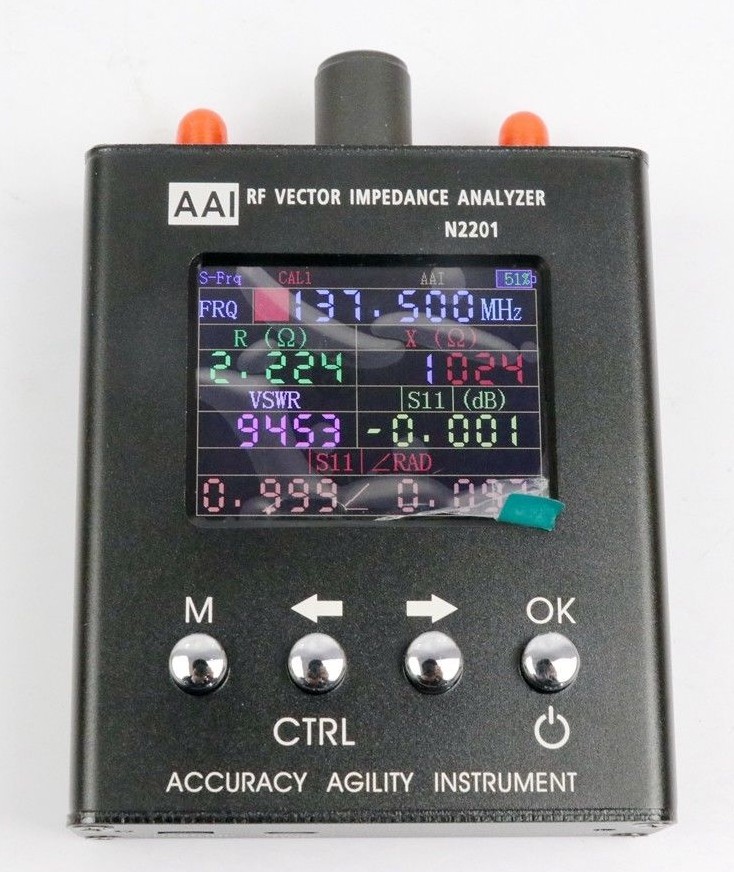
DIY Antenna Analyzer

have a look at something like this to generate (SPI) an wide range RF signal

I am hoping it would be that simple. My first skim through the data sheets, LMIC libs and Radio Head libs. though are leaving me with more questions than answers.

Having said that those libs are doing a lot more than I need the module to do.

Some of this may have to be a case of cribbing the useful stuff out of the headers and then trialling some stuff.

I understand what you are trying to achieve and the basic principles are good … but … a lot of 'but’s :wink:

That looks promising and a nice wide RF range. Will keep that one in mind for when the RFM95W proves to be too low an output to work with.

True

But it has got to start somewhere, and then iterate till we find a workable solution. If there is one. The key aim is to produce a cost effective antenna analyser for the home made antenna builds.

true… it’s a complicated project I think.
in fact you want to build this

antenna-analyzer

1 Like

There is a great article on RTL-SDR based antenna analyzer.

It is sufficient to purchase:

  • BG7TBL noise source
  • Directional coupler
  • R820T DVB-T USB stick

This is an example of “return loss vs frequency” for antenna that comes with TTGO LoRa32 V2 :

antenna_ttgov2

2 Likes

What frequency was the unit and antenna supposed to work at ??

Nice article though, well spotted. Just had a skim through.

I already have an RTL SDR device and can see more uses for that sort of setup than Antenna Analysis.

Overall though I am aiming at a device for around £20. Cheap, nasty, simple and works. TBH I am only using a teensy as I had one lying around and wanted to use up the last 3.1 I had before moving on to similar with a better regulator on board.

look what you’ve done when I go to ebay now :sunglasses:

lol

2 Likes

Lol that is looking expensive. Put a padlock on the wallet and keyboard.

Radio is complicated, that and building stuff is where most of the fun is though.

I have copied the link on the RTL SDR methods to the radio guys at our Hackspace, there are a few of them with SDR setups. So this will be of interest to them. Thanks Linar.

This is the setup I have been using, and I am getting usable results.
image

1 Like

I did produce a signal generator using a LoRa device for testing a filter a few months back, you will find it here, its a standalone program;

https://github.com/LoRaTracker/Test-Programs

Its not very fast, and it ought to be possible to make it shift frequency faster, but I did not investigate that too far.

The issue with using a LoRa device is not that it does not have enough power, but the opposite. I was using an RF Explorer as the receiver, and you do not want to be injecting 17dBm into such a device or indeed an SDR, so you will need an attenuator.

What frequency was the unit and antenna supposed to work at ??

868 MHz band :smiley:

yes I knew I had seen that rf bridge before :sunglasses:

I already have an RTL SDR device…
Overall though I am aiming at a device for around £20…

Factory built couplers are starting from 9 USD. I’ve managed to use this one

Noise source costs about 11 USD

Add few USDs more for N-SMA adapters like this , that and pigtail .

So you will likely stay within your £20 budget.

BoRRoZ, that is a serious eBay habit you have there. LOL

I am seeking help for my Aliexpress habit, I go to AA (Aliexpress Anonymous) meetings on a weekly basis now. Aliexpress’s retail therapy has been very supportive and helpful while I work through my addiction… :heart_eyes:

LoRaTracker, that sig gen code looks like a very good starting point, many thanks. I had a quick rummage through your repo of codes and projects there, it is pretty awesome.

Linar, On the TTGO antenna I was struggling to see the peak/dip around 868, think I still am LOL. On the whole I have generally had quite good experiences getting stuff from china, sometimes though things are not quite what they seem. Having a way to be able to check for sure is priceless.

We have lashed up a full gateway in the Hackspace for the members to use and the sensitivity + signal is very poor with the antenna it came with, even alowing for it being indoors. I am starting to become suspicious that the antenna is a wifi one that ended up in the wrong bin at the warehouse. We have bent up a co-linear from the TTN design but I want to test it before we try to use it in anger.

I have ordered up a noise source and a coupler from Aliexpress, but having seen that particular one from transverters I think I will have one of those as well. Not terribly expensive and a reasonable spec. Besides this project there are a whole bunch of other things I want to do that having a noise source, coupler and SDR spectrum analyser will be very useful for.

I am planning on continuing on with this particular project for now as well though.I am sufficiently interested by resistive impedance bridge measurements to want to to see it through. The SDR + Noise Source and coupler though will be useful to see what the resistive bridge looks like across a wide frequency range. My experiences of working with fast pulses in the time domain have shown that a nice resistive termination can give a very useful degree of wide bandwidth. Depending on the construction and quality of the resistors of course.

A resistive unit and a canned sig generator is a useful thing for newbies to start out with too, it can take a while for folk new to radio to bend their heads around the esoterica of impedance, resonance, directional couplers and transmission line transformers. Although there are unquestionable benefits for toughing it out, making the journey and getting there. Some toeholds along the way that borrow from simpler electronics can be useful if only as a way to instruct and ease the journey.

Apologies illperipherals, I left your name of the acknowledgements there. Nice piccy.

Am just rebuilding an old notebook as a dedicated RTL-SDR machine. For a similar rig.

I doubt that the resistive bridge you made is usable at UHF frequencies. Resistors at UHF have a lot of inductive and/or capacitive reactance . You need special microwave resistors without leads.

Agreed

Even on the carbon composition resistors i have used i should expect some loss of high frequency capability due to having leads, before we even get into the wiring on the board.

The SDR rig as discussed above will be useful to determine where it is all at, and enable tweaking of a design till it gets to where I want it to be.

An end result will look nothing like this first random rough cut. But should still be cheap, understandable and DIY-able.