I have built a simple Antenna Analyser circuit based on :-
I was hoping to use an RMF95W (868MHz) module as the Signal Generator. Simply as this is what I have to hand. But am open to working with another module if the RFM95W wont work. This does presume though that the module can be programmed in some way to produce a steady carrier at a programmed frequency.
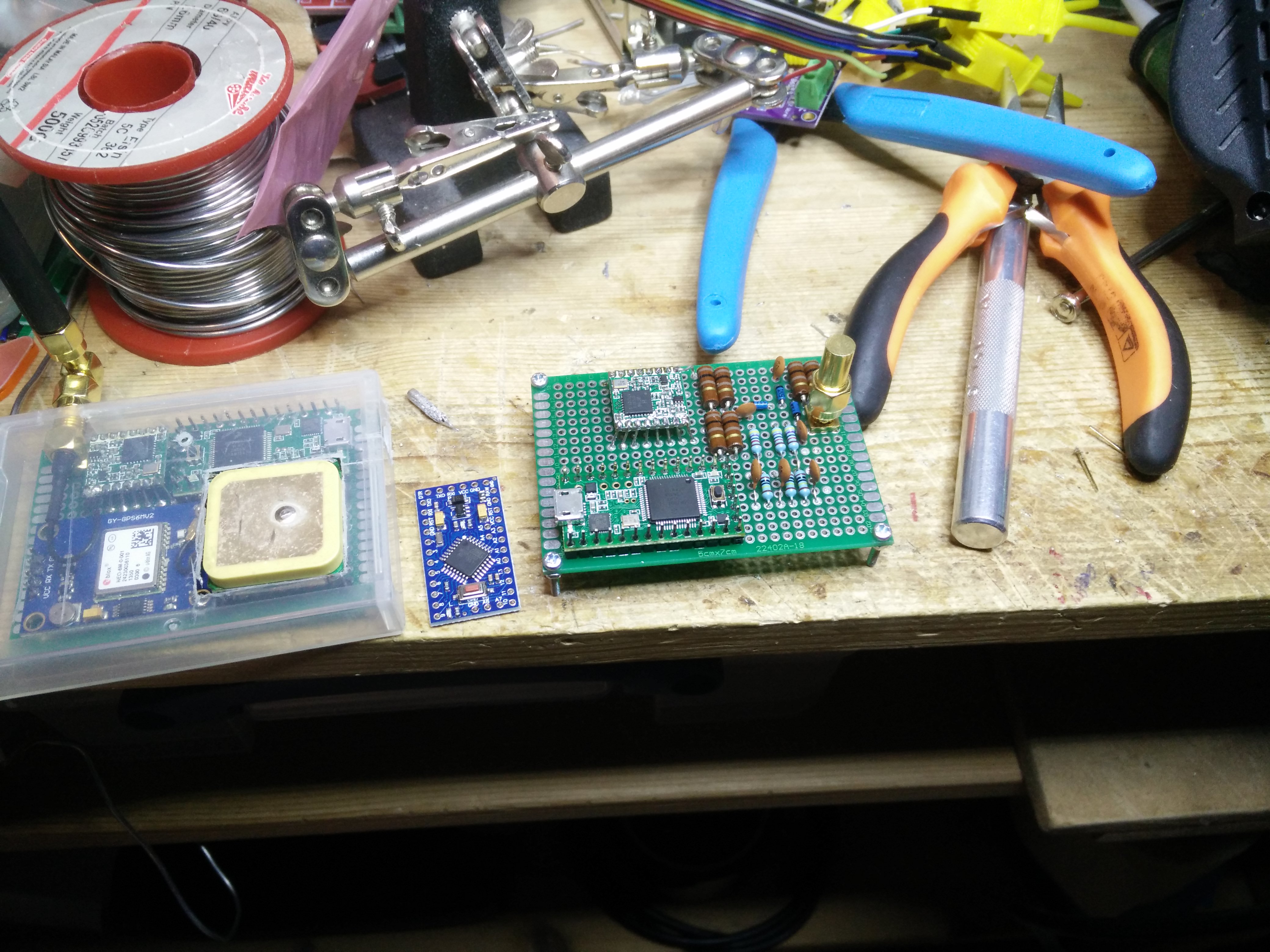
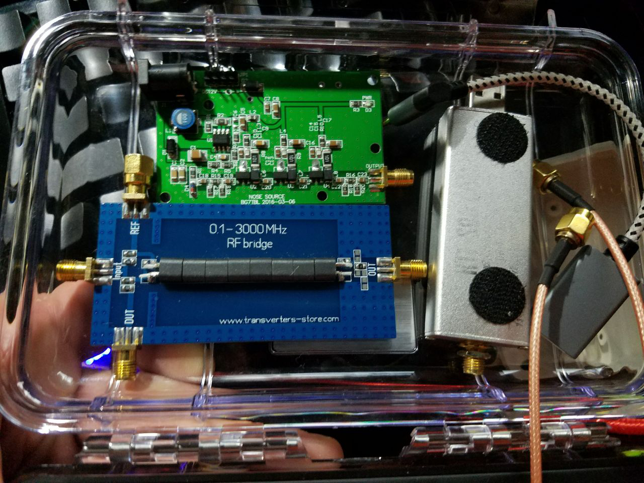
So far I have the bridge circuit built up and 3 off the signal conditioning circuits attached, just dropped a teensy onto the board and the RFM95W (868MHz) module.
But before connecting it all up I have been having a dig around to see if there is already code for this type of application. Not found anything yet.
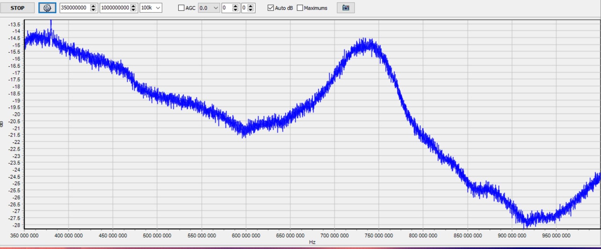
In it’s simplest form I want the radio module to produce a low power rf carrier and to program sweeping that frequency across the modules available range. whilst taking Vrv Vrm and Vz measurements at each frequency step.
I can pull these off via USB and then plot them to give an analysis of the antenna.
Has anyone tried this already ?
Does anyone know of code examples ready to go for this type of application ?
Anyone else fancy having a play with something like this ?
just curious because we are dealing with very high frequencies (up to 1 Ghz) … how did you build that. ? can you show a picture of your build to get an idea .
you probably can’t use the RFM95W to measure antenna refelection because its rf output is to low
In it’s simplest form I want the radio module to produce a low power rf carrier and to program sweeping that frequency across the modules available range
Its not difficult, set the LoRa device up in direct mode, turn on transmit and just keep writing the changes to the frequncy setting registers.
LOL the simple answer is probably not well enough and certainly not on a breadboard.
I used a smallish proto FR4 board that only has pads and no strips to keep the capacitance down, along with short lead lengths. Whether it will be enough is yet to be seen. As per the statement it is experimental.
I am relying on the whole thing being mostly a resistive bridge. A later rework will probably have to be done using more usual RF construction techniques, or a custom PCB.
I am hoping it would be that simple. My first skim through the data sheets, LMIC libs and Radio Head libs. though are leaving me with more questions than answers.
Having said that those libs are doing a lot more than I need the module to do.
Some of this may have to be a case of cribbing the useful stuff out of the headers and then trialling some stuff.
But it has got to start somewhere, and then iterate till we find a workable solution. If there is one. The key aim is to produce a cost effective antenna analyser for the home made antenna builds.
Nice article though, well spotted. Just had a skim through.
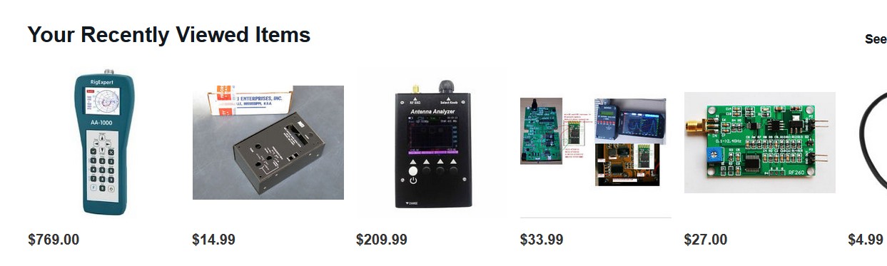
I already have an RTL SDR device and can see more uses for that sort of setup than Antenna Analysis.
Overall though I am aiming at a device for around £20. Cheap, nasty, simple and works. TBH I am only using a teensy as I had one lying around and wanted to use up the last 3.1 I had before moving on to similar with a better regulator on board.
Lol that is looking expensive. Put a padlock on the wallet and keyboard.
Radio is complicated, that and building stuff is where most of the fun is though.
I have copied the link on the RTL SDR methods to the radio guys at our Hackspace, there are a few of them with SDR setups. So this will be of interest to them. Thanks Linar.
Its not very fast, and it ought to be possible to make it shift frequency faster, but I did not investigate that too far.
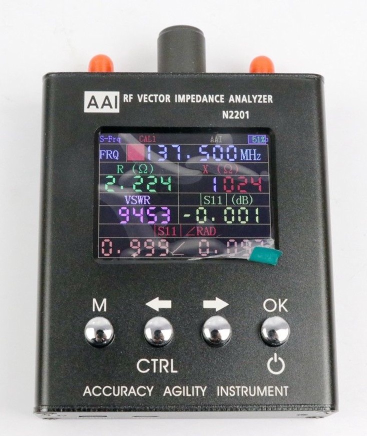
The issue with using a LoRa device is not that it does not have enough power, but the opposite. I was using an RF Explorer as the receiver, and you do not want to be injecting 17dBm into such a device or indeed an SDR, so you will need an attenuator.