DIY Antenna Analyzer

BoRRoZ, that is a serious eBay habit you have there. LOL

I am seeking help for my Aliexpress habit, I go to AA (Aliexpress Anonymous) meetings on a weekly basis now. Aliexpress’s retail therapy has been very supportive and helpful while I work through my addiction… :heart_eyes:

LoRaTracker, that sig gen code looks like a very good starting point, many thanks. I had a quick rummage through your repo of codes and projects there, it is pretty awesome.

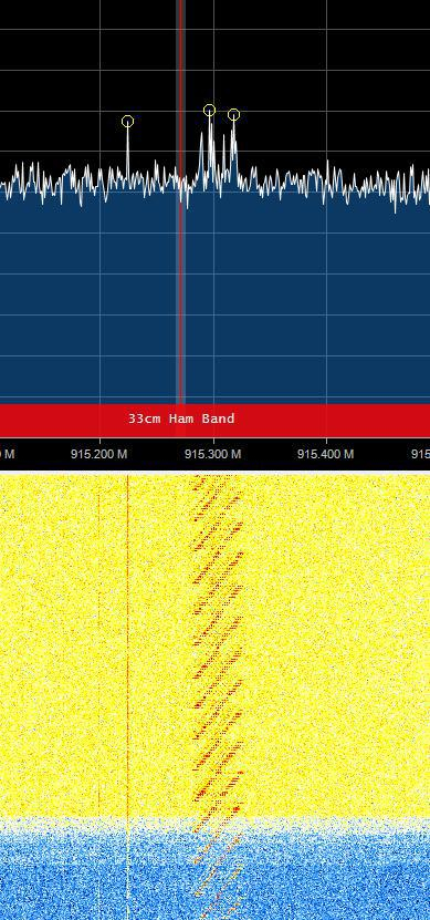
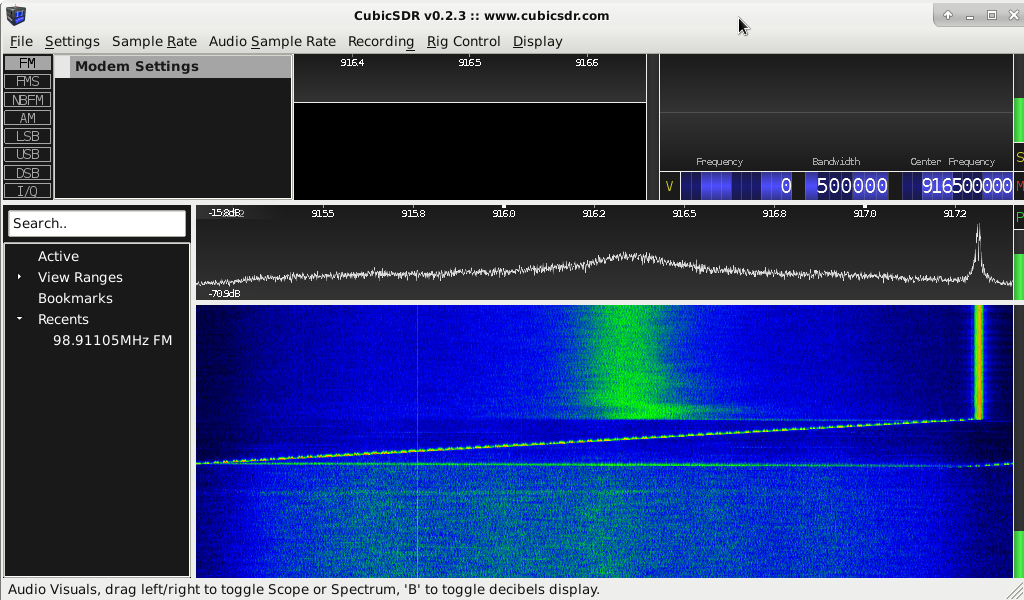
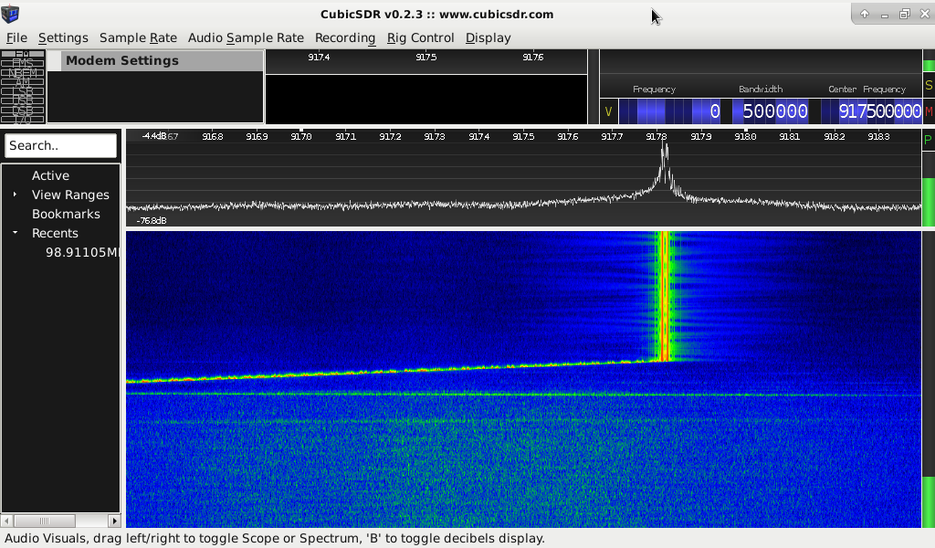
Linar, On the TTGO antenna I was struggling to see the peak/dip around 868, think I still am LOL. On the whole I have generally had quite good experiences getting stuff from china, sometimes though things are not quite what they seem. Having a way to be able to check for sure is priceless.

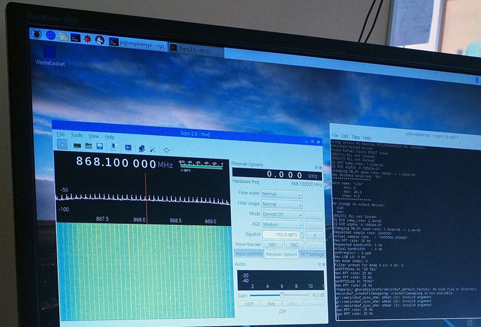
We have lashed up a full gateway in the Hackspace for the members to use and the sensitivity + signal is very poor with the antenna it came with, even alowing for it being indoors. I am starting to become suspicious that the antenna is a wifi one that ended up in the wrong bin at the warehouse. We have bent up a co-linear from the TTN design but I want to test it before we try to use it in anger.

I have ordered up a noise source and a coupler from Aliexpress, but having seen that particular one from transverters I think I will have one of those as well. Not terribly expensive and a reasonable spec. Besides this project there are a whole bunch of other things I want to do that having a noise source, coupler and SDR spectrum analyser will be very useful for.

I am planning on continuing on with this particular project for now as well though.I am sufficiently interested by resistive impedance bridge measurements to want to to see it through. The SDR + Noise Source and coupler though will be useful to see what the resistive bridge looks like across a wide frequency range. My experiences of working with fast pulses in the time domain have shown that a nice resistive termination can give a very useful degree of wide bandwidth. Depending on the construction and quality of the resistors of course.

A resistive unit and a canned sig generator is a useful thing for newbies to start out with too, it can take a while for folk new to radio to bend their heads around the esoterica of impedance, resonance, directional couplers and transmission line transformers. Although there are unquestionable benefits for toughing it out, making the journey and getting there. Some toeholds along the way that borrow from simpler electronics can be useful if only as a way to instruct and ease the journey.

Apologies illperipherals, I left your name of the acknowledgements there. Nice piccy.

Am just rebuilding an old notebook as a dedicated RTL-SDR machine. For a similar rig.

I doubt that the resistive bridge you made is usable at UHF frequencies. Resistors at UHF have a lot of inductive and/or capacitive reactance . You need special microwave resistors without leads.

Agreed

Even on the carbon composition resistors i have used i should expect some loss of high frequency capability due to having leads, before we even get into the wiring on the board.

The SDR rig as discussed above will be useful to determine where it is all at, and enable tweaking of a design till it gets to where I want it to be.

An end result will look nothing like this first random rough cut. But should still be cheap, understandable and DIY-able.

I have been trying to make a usable antenna analyzer for 868MHz. I wanted to use it without a PC/laptop so no RTLSDR as detector.
I worked with a ADF4350 generator board, a 0.5-3000MHz RF-bridge and a AD8318 as logaritmic detector. That did not work, the ADF4350 is square wave output, so a lot of uneven harmonics that masks the reflection measurements. Also the ADF4350 board did only have about zero dBm output. Reflected signals travels twice through the RF-bridge, so 6dB powerloss there, so I needed a amplifier. To eliminate the harmonics I used a 1200MHz low pass filter.

By that time I was so disappointed by the poor results of this setup that I bought a N1201SA antenna analyzer which works very well.

The N1201SA works with two ADF4350 generators. One for the signal and the second mixes the reflected signal down to a low intermediate frequency. So the detector only sees the measured frequency and is not influenced by other (f.i. GSM) signals that are received on the antenna under test.

costo, I use a USB-OTG adapter with my android phone (Galaxy S7 Active).
It is the grey/black cable on the above pic. That is why I have the velcro on the SDR :wink:
Works fine with a number of programs using Rtl-sdr driver.
image

I tried this article https://www.rtl-sdr.com/rtl-sdr-tutorial-measuring-filter-characteristics-and-antenna-vswr-with-an-rtl-sdr-and-noise-source/ - take a look at my post from February - The BIG and SMALL ANTENNA topic part 1

Which software did you use for the spectrum capture and is that trace calibrated (the signal without the antenna subtracted) ??

Nicbkw

I had seen that article but must admit at the time i was more focused on the antenna’s than the rig. Not the sort of rig you can whip out of your back pocket up a ladder whilst clinging on with your teeth. But still very useful non the less. This plus mobile use and a self contained small unit was what motivated the resistive bridge direction.

I think Costo was thinking along similar lines at some point too.

Which software did you use for the spectrum capture

rtlpan for Windows. The software that is referenced by the article.

and is that trace calibrated (the signal without the antenna subtracted)

Not yet.
With open coupler output, reflected signal’s spectrum was rather linear within 300-1000 MHz range. Variations were: 1-3 dB
So the noise source is quite good for the price spent.

You may also consider to use a dummy load and see the reference bottom line of the chart.

I have ordered up … a coupler from Aliexpress…

Make sure the coupler is going to meet your expectations.
The item I’ve referenced onto has declared 800-2500 MHz operating range.
In fact it is usable staring from 300-350 MHz (or at least my sample).
If you need 2 meters band and/or CB - I should probably look for a better one.

Had a grub around yesterday for a decent all in one spectrum analyzer package for Linux and found a lot of stuff that was halfway there. Basicaly spectrum collector/viewers, Spektrum looked like it was going to be doable and the write up suggested it would take a baseline and subtract it, but getting it to run, was past the point at which the will to live left me.

In other lives MCA (Multi Channel Analyser or spectrum analysis software) allows you to save spectra and do basic spectra math, like subtract that spectrum from this or add this to that, rebin etc etc etc. All very much doable once you have collected a spectrum. Especially on a PC. Such desirable features I am a bit blown away as to why they have not been done for rtlsdr spectra.

Anyway onwards and upwards, got stuff to build.

Yes was aware of this.

On directional couplers. Given that in this instance we are not really too worried about the wideband characteristics so long as it is centred on 868MHz and is wide enough to tell us which way to tune an antenna. I think there is a case to be made for an 868MHz specific home made coupler, to get new folk started with.

1/4 wave length at 868 is not that long. So a pair of stiff copper wires, 4 SMA bulkhead connectors and a metal case (maybe a larger diameter copper pipe, or some such) maybe doable. Still needs someone with a fuller test setup to test the design though.

The ultimate in wideband devices is great and I buy into that idea completely, however sometimes an inexpensive, fun to build from available stuff, just good enough for the job type thing is more fun and is a great learning opportunity.

Probably I will try that once I have a new phone. Still i am not impressed by the quality of the RTLSDR, it suffers from harmonic mixing and IM that will blur the results of your measurements.

For the price, £5, I am impressed with the capabilities of the RTL SDRs.

There are more expensive options.

Sure the RTLSDR is versatile with the right software, (like a multimeter)
But look at the picture in this link RTL-SDR Tutorial: Measuring filter characteristics and antenna VSWR with an RTL-SDR and noise source
of a 1090MHz bandpass filter. Around 400MHz you see a response that should not be there, it is exact 1/3 of the main response. If you use a RTLSDR for filters or SWR measuring you cannot expect accuracy better than ± 5%.

I would not be very happy with a multimeter that can be ±5% inaccurate.

I think the accuracy can be improved by inserting a LowPassFilter between the NoiseSourse and the RF-Bridge, like this filter: https://www.aliexpress.com/item/1-4Ghz-Low-Pass-Filter-For-1-2Ghz-System-FPV-RC-AV-Transmitter-LPF-For-FPV/32797159270.html

edit: Ofcourse you can better have a multimeter which you know that can be 5% inaccurate than to have no multimeter at all :wink:

Ok Guys some initial results.

I borrowed heavily from LoRaTracker’s code as linked earlier in this thread. So far I have not modified it terribly except reformatting the code so it work’s better with my dyslexia and trimming out any functions etc. that were not called.

First piccy is of the end of the sweep with the test port connected to an SMA 50 Ohm terminator:-

endsweeptrm

Second piccy is of the end of the sweep with the test port connected to one of those little rubber ducky entenna;s that come t=with the 868MHz ESP32 modules :-

endsweepant

For both the piccys I was using a not ideal antenna (RG174, double Bazooka, 433MHz) because it was what I had to hand connected up to my RTLSDR across the room.

Not got around to trying to measure any voltages as yet, one step at a time.

Observations:-

Whether running into a terminator or into an Antenna the lead lengths are long enough to radiate. Using SMD components, impedance matched traces as well as shorter runs and having a ground plane have got to be helpful.

Running into an antenna produces a stronger signal than into the terminator so some degree of antenna analysis may be possible as is. But the circuit could do with being better constructed.

This is on the lowest power setting according to the code I have pinched (2dbm).

The power spike (yes there are some other much weaker artefacts I think), seems to be sat reasonably reliably on the frequency it was set for.

Could do with a way to shut the TX off between actual sweeps to save pumping out pointless rfi.

Interesting first results though.

gqrx

And using my expendable multimeter on milivolts range we have:-

Test, Vz, Vrm, Vrv, Units
Antenna,14, 79.1, 77.3, mV
OC, 73.8, 70.8, 55.7, mV
50Ohm, 85.6, 66.8, 14, mV

This was simply as I have not connected up the analogue inputs to the teensy3.1 just yet till I could get a handle on how much voltage we would see at each test point.

I took the measurements with the rf output into the test port, static at 918MHz.

Although the compiler will check the ‘unused’ routines, if they are not actually used they are removed by the complier.

Agreed, my optical neural reader though is stuffed.

LOL

2 Likes