Hi @bauvill
on Raspberry , have you installed “/bokse001/dual_chan_pkt_fwd” ?
My project uses this software for the gateway, it’s the most important part, to use the “downstream message”
Hi @bauvill
on Raspberry , have you installed “/bokse001/dual_chan_pkt_fwd” ?
My project uses this software for the gateway, it’s the most important part, to use the “downstream message”
Thanks once more.
My gateway runs the forwarder software from (“/bokse001/dual_chan_pkt_fwd”) but issues at this level was : packets received at the gateway layer on a frequency such as 866.1 or any other frequency different from 868.3 were all shown in the gateway logs as packets sent on the frequency 868.3, as a result, the server routes the downlink packets to that frequency. That should be where my problem lies.
I have carried out some modification on the gateway ( setting the _STRICT_1CH = 1 instead of _STRICT_1CH =0 which was the default value).
I am still about to test it on my node.
Thanks for your support.
Hi
these are the sensor and gateway logs when I did the tests
OUTPUT SERIAL ATOM HELTEC32 con ricezione DownStream message
10101683: engineUpdate, opmode=0x908
10101731: TXMODE, freq=868100000, len=23, SF=7, BW=125, CR=4/5, IH=0
Packet queued
10161952: RXMODE_SINGLE, freq=868100000, SF=7, BW=125, CR=4/5, IH=0
10218564: RXMODE_SINGLE, freq=869525000, SF=9, BW=125, CR=4/5, IH=0
10244705: EV_TXCOMPLETE (includes waiting for RX windows)
bytes of payload: 0x
10244710: engineUpdate, opmode=0x900
12119710: engineUpdate, opmode=0x908
12119758: TXMODE, freq=868100000, len=23, SF=7, BW=125, CR=4/5, IH=0
Packet queued
12179979: RXMODE_SINGLE, freq=868100000, SF=7, BW=125, CR=4/5, IH=0
12189361: Received downlink, window=RX1, port=1, ack=0
12189371: EV_TXCOMPLETE (includes waiting for RX windows)
Received
3
bytes of payload
bytes of payload: 0x000102
12189632: engineUpdate, opmode=0x800
14064632: engineUpdate, opmode=0x808
14064680: TXMODE, freq=868100000, len=23, SF=7, BW=125, CR=4/5, IH=0
Packet queued
14124902: RXMODE_SINGLE, freq=868100000, SF=7, BW=125, CR=4/5, IH=0
14181513: RXMODE_SINGLE, freq=869525000, SF=9, BW=125, CR=4/5, IH=0
14207650: EV_TXCOMPLETE (includes waiting for RX windows)
bytes of payload: 0x
14207655: engineUpdate, opmode=0x900
OUTPUT GATEWAY01 con ricezione Downstream message
stat update: 2018-03-27 20:46:03 GMT 5 packets received, 0 packet sent…
CE0 Packet RSSI: -36, RSSI: -104, SNR: 9, Length: 23 Message:rxpk update: {“rxpk”:[{“tmst”:4212123479,“freq”:868.3,“chan”:0,“rfch”:0,“stat”:1,“modu”:“LORA”,“datr”:“SF7BW125”,“codr”:“4/5”,“rssi”:-36,“lsnr”:9.0,“size”:23,“data”:“QFsRASaAAwABjDJ01tnrMyOjfhbubvA=”}]}
stat update: 2018-03-27 20:46:33 GMT 6 packets received, 0 packet sent…
CE0 Packet RSSI: -47, RSSI: -97, SNR: 9, Length: 23 Message:rxpk update: {“rxpk”:[{“tmst”:4244415677,“freq”:868.3,“chan”:0,“rfch”:0,“stat”:1,“modu”:“LORA”,“datr”:“SF7BW125”,“codr”:“4/5”,“rssi”:-47,“lsnr”:9.0,“size”:23,“data”:“QFsRASaABAAB0bMQfYyQzR9XHc114hM=”}]}
stat update: 2018-03-27 20:47:03 GMT 7 packets received, 0 packet sent…
CE0 Packet RSSI: -45, RSSI: -100, SNR: 9, Length: 23 Message:rxpk update: {“rxpk”:[{“tmst”:4276705521,“freq”:868.3,“chan”:0,“rfch”:0,“stat”:1,“modu”:“LORA”,“datr”:“SF7BW125”,“codr”:“4/5”,“rssi”:-45,“lsnr”:9.0,“size”:23,“data”:“QFsRASaABQABBcRMhLqXGcj8QZNlTIY=”}]}
stat update: 2018-03-27 20:47:33 GMT 8 packets received, 0 packet sent…
CE0 Packet RSSI: -43, RSSI: -97, SNR: 8, Length: 23 Message:rxpk update: {“rxpk”:[{“tmst”:14027286,“freq”:868.3,“chan”:0,“rfch”:0,“stat”:1,“modu”:“LORA”,“datr”:“SF7BW125”,“codr”:“4/5”,“rssi”:-43,“lsnr”:8.0,“size”:23,“data”:“QFsRASaABgABT7eMr79xFNcu5Yl4iE0=”}]}
Sending packet:: tmst=15027286, wait= -1507156382, strict=0, datr=SF7BW125, freq=868300000->868300000, sf=7->7, modu=LORA, powe=14, codr=4/5, ipol=1, through CE1.
PKT_PULL_RESP:: From server router.eu.staging.thethings.network.
stat update: 2018-03-27 20:48:03 GMT 9 packets received, 1 packet sent…
CE0 Packet RSSI: -43, RSSI: -97, SNR: 9, Length: 23 Message:rxpk update: {“rxpk”:[{“tmst”:45146368,“freq”:868.3,“chan”:0,“rfch”:0,“stat”:1,“modu”:“LORA”,“datr”:“SF7BW125”,“codr”:“4/5”,“rssi”:-43,“lsnr”:9.0,“size”:23,“data”:“QFsRASaABwABXd/KTwbnvgAmhUtl0wY=”}]}
stat update: 2018-03-27 20:48:33 GMT 10 packets received, 1 packet sent…
Thanks for the screenshots. my gateway outputs are the same but my node seems not to be getting anything. Is your node listening/sending on one frequency or all frequencies? Do you think I should the value my receive windows??
When a node sends on the frequency 868.1 does listen to the server reply on the same frequency? I asking because I have limited my node to send on a single channel. Is it wrong?
This function does not exist in my code LMIC_setClockError (MAX_CLOCK_ERROR * 10/100);
Are you sure you are reading the log correctly? You could interpret the marked line as no packets being sent to a downlink node (that is the way I interpret it). And that is probably because the back-end never instructed the gateway to send any data.
Yes and no. The first receive window (1 second after transmit) is at the same frequency. The second window (2 seconds after transmit) is at 869.525MHz with SF9. (So you should not set your gateway to pure 1 channel as this disallows switching to the right frequency for RX2)
Something else, if your node and your gateway are too close the gateway will receive data on a channel the node is not sending on. Make sure there is at least 3 meters space between the gateway and the node. And change the code on your node and gateway to use SF7 to SF9, SF12 is rarely needed and not good while testing with hardware in close vicinity.
I would be surprised if your code will receive anything at all without that line.
@bauvill
I sent you a message with the sketch I used in the sensor for the test,
maybe he can help you.
Sorry for the comments lines in Italian 
Do I need to make an application to have the gateway to be instructed to forward the messages it get? I made an application and when I register the same gateway it doe not show that it is connected whereas in the Gateway console it shows connected and the gateway does not show any traffic in the console.
Thank you, sir.
No, the gateway will always forward all messages to TTN.
My node is made based on RPI +DRAGINO and the LMIC library for repair the function LMIC_setError is not defined in the LMIC API. Do I need to implement it myself?
Maybe that is why it does not work.
It is actually in the LMIC library just most likely not the version you are using. I have come across this issue a couple times now within the last couple weeks. The LMIC library that is available just by searching through the Arduino IDE Manage libraries option does not have this code setup. Everyone here when they point you to a TTN - LMIC example are using the updated version that includes the ability to implement the setClockError “add” which means you’ll need to update your library files to the ones they are referring to.
Note: This is as far as I can tell from my own copy of the Arduino IDE
Is it present only in the LMIC library for Arduino?
Asking because I am not using Arduino but Raspberry Pi.
Thanks for the clarification though.
The simplest ways of checking that might just be to open up the LMIC files on your Pi and search if there is a MAX_CLOCK_ERROR set somewhere, in the Arduino libs it’s easy to see if it’s implemented or not in the LMIC.h file. So for the Pi if it’s using similar C++ files you should be able to find it. But if it’s not there, that’s not the only place there is probably a bit of code missing relating to that issue which means you might have to do some digging.
Also this clock Error issue is one that is very much more rooted in the Arduino side of things and not the Raspberry Pi (though the different versions have their own issues) because it’s been implemented to check the timing crystal and it’s variations used in the official and ‘off-brand’ versions of their boards.
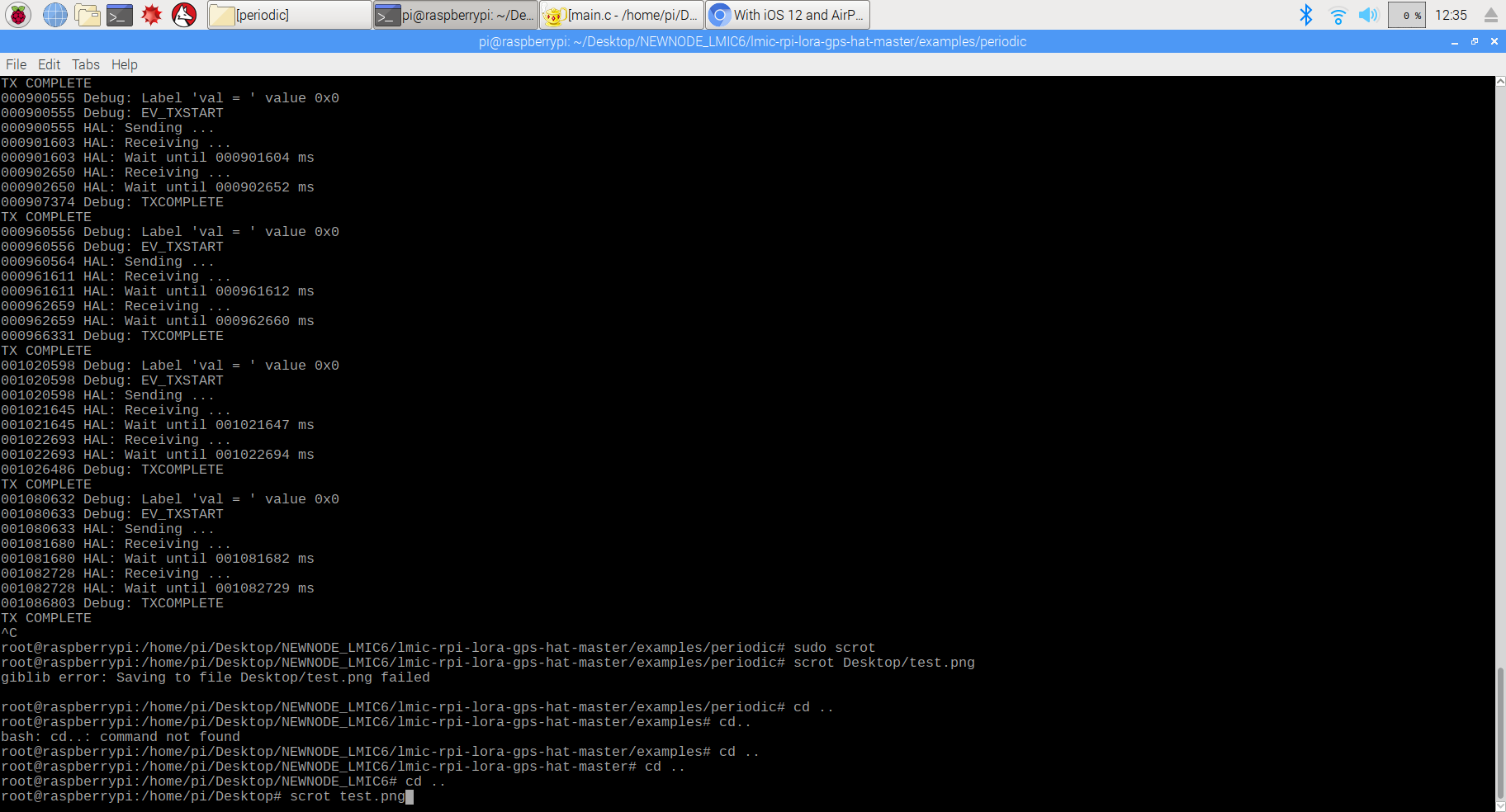
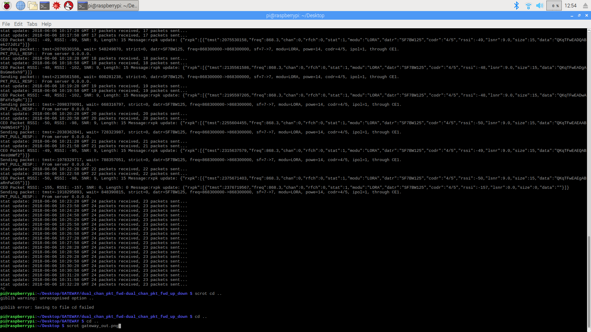
I am using RPI 3B + dragino HAT V1.4 running the dual_chan_pkt_fwd ( as Batigolle described in his post related to this topic), as of the end-device ( Lora node) same components ( RPI 3B +Dragino HAT V1.4) are used. It is to be noted that my end device runs the ABP LMIC v1.6 version from ( https://github.com/wklenk/lmic-rpi-lora-gps-hat/blob/master/examples/periodic/main.c). I will give you more details or screenshots of my code, logs of my end device and gateway in the next post.
1 - This is the code running on my end-device
#include <stdio.h>
#include "lmic.h"
#include "debug.h"

// sensor functions
extern void initsensor(void);
//extern u2_t readsensor(void);


//////////////////////////////////////////////////
// CONFIGURATION (FOR APPLICATION CALLBACKS BELOW)
//////////////////////////////////////////////////

//NOTE: these values are used for testing on my local LoraWAN server
static const u1_t APPEUI[8]  = { 0x6B, 0xF3, 0x00, 0xD0, 0x7E, 0xD5, 0xB3, 0x70 };
static const u1_t DEVEUI[8]  = { 0xFF, 0x85, 0xEF, 0xFF, 0xFF, 0xEB, 0x27, 0xB8 };
static const u1_t DEVKEY[16] = { 0x4A, 0x10, 0xBA, 0x2E, 0x74, 0x3D, 0x28, 0xDF, 0x9C, 0xA9, 0xA2, 0xC2, 0x27, 0xE2, 0xAD, 0x2B };
static const u1_t ARTKEY[16]  ={ 0x36, 0x2F, 0x66, 0x8D, 0x1C, 0xC4, 0x08, 0x5C, 0x11, 0x31, 0x66, 0x91, 0xC4, 0xC1, 0x3D, 0xB3 };
static const u4_t DEVADDR = 0x011793AA; // <-- Change this address for every node!


// provide application router ID (8 bytes, LSBF)
void os_getArtEui (u1_t* buf)
 {
    memcpy(buf, APPEUI, 8);
}

// provide device ID (8 bytes, LSBF)
void os_getDevEui (u1_t* buf)
{
    memcpy(buf, DEVEUI, 8);
}

// provide device key (16 bytes)
void os_getDevKey (u1_t* buf)
{
    memcpy(buf, DEVKEY, 16);
}


void setup()
{
  os_init();
  // Reset the MAC state. Session and pending data transfers will be discarded.
  LMIC_reset();

  // by joining the network, precomputed session parameters are be provided.
  LMIC_setSession (0x1, DEVADDR, (u1_t*)DEVKEY, (u1_t*)ARTKEY);
  // Disable data rate adaptation
   LMIC_setupChannel(0, 868100000, DR_RANGE_MAP(DR_SF12, DR_SF7),  BAND_CENTI);
  LMIC_setAdrMode(0);
  // Disable link check validation
  LMIC.dn2Dr = DR_SF9;
  LMIC_setLinkCheckMode(0);
  // Disable beacon tracking
  LMIC_disableTracking ();
  // Stop listening for downstream data (periodical reception)
  LMIC_stopPingable();
  //LMIC_setClockError(MAX_CLOCK_ERROR * 10 / 100);  <------------------------Not implemented
  // Set data rate and transmit power (note: txpow seems to be ignored by the library)
  LMIC_setDrTxpow(DR_SF7,14);

}


//////////////////////////////////////////////////
// UTILITY JOB
//////////////////////////////////////////////////

static osjob_t reportjob;

// report sensor value every minute
static void reportfunc (osjob_t* j)
{
    // read sensor
    //u2_t val = readsensor();
    u2_t val = 0x0; // This is for testing only. this function will send the state(e.g 0%,30%, or 100%)  of a
   //component it will be connected to.
    debug_val("val = ", val);
    // prepare and schedule data for transmission
    LMIC.frame[0] = val >> 8;
    LMIC.frame[1] = val;
    LMIC_setTxData2(1, LMIC.frame, 2, 0); // (port 1, 2 bytes, unconfirmed)
    // reschedule job in 60 seconds
    os_setTimedCallback(j, os_getTime()+sec2osticks(60), reportfunc);
}


void onEvent (ev_t ev)
{
    debug_event(ev);
    switch(ev) {

      case EV_TXCOMPLETE:
          // switch on LED
          debug_led(1);
          if (LMIC.txrxFlags & TXRX_ACK)
         {
			  fprintf(stdout, "ACK RECEIVED\n");
	  }
          fprintf(stdout, "TX COMPLETE\n");
          if(LMIC.dataLen)
         { // data received in rx slot after tx
              //debug_buf(LMIC.frame+LMIC.dataBeg, LMIC.dataLen);
              fprintf(stdout, "Data Received!!!!!!!!!!!!!!!!!!!!!!!!!!!!!!!\n");
         }
          break;
    default:
          break;
    }
}
void loop()
 {

reportfunc(&reportjob);

 while(1)
 {
  os_runloop();

  }
}


int main()
{
  setup();

  while (1)
  {
    loop();
  }
  return 0;
}
2- The screenshot of logs on the End-device
2- The output on my gateway
Can you explain why can’t I see any data on the gateway console in TTN?
Not with the information I have available at this moment.
Hi all!
first of all, thanks for your tutorial.
I’m following this tutorial with a RPI3B+ and a Dragino HAT v1.4, everything seems to work, but it shows this at the transceiver version:
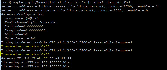
And and I do not receive node data.