Hi,
I have a new Adafruit Feather 32u4. I’m trying to get it working for over a week now. I’m in Europe, specifically in Bratislava, Slovakia. I’m using the TinyLoRa library from Adafruit and ABP method to send the data.
I have tried many things: changing the channel, changing the frequency, changing the datarate, going 20m away from the gateway, creating a new aplication… but I still can’t get it working.
Is there anyone who lives in Europe and (succesfully) uses a Adafruit Feather 32u4? I could really use your help.
So:
I’ve read through the thread you posted. I have created and setup both the TTN app and device. I’ve read a couple of other threads and tutorials.
I have some questions:
Here Adafruit states that you don’t need a jumper between the pin 6 and io1 when using feather 32u4, only when using feather M0. But everyone seems to use it anyway. Why is that?
From what I have read, you can set the datarate from SF7BW125 to SF12BW125 with SF12BW125 giving higher “privilige” and therefore bigger range. Is that correct?
In the link above, Adadfruit suggests using the TinyLoRa library for the 32u4. It’s a library specifically for the 32u4. It uses less space and it is much simpler. Should a use that or should I use the standard LMIC library?
Like at the moment? No. My home is aproximatelly 3.7km away from the nearest gateway so I can not do testing from here. I already tested it a couple of times before very close to the gateway. Now, I’m trying to get more information so I’ll be prepared next time.
The tutorial you sent is for the M0, but I suppose that the process with the 32u4 is similar aside from the different board selection and different wiring.
Hmm, with the TinyLoRa library I get just “Sending LoRa Data…” and “Frame Counter: x” but that is expected because it’s supposed to be a small library so it doesn’t have many debugging options.
But even using the LMIC library, I never got nothing which said that it’s joining. I did get only “EV_TXCOMPLETE (includes waiting for RX windows)” and “Packet queued” on the serial monitor. Weird.
How should the output look like when it’s working correctly?
first thing is that your device is registered with the network.
you do that through the console… add application ’ test ’ with device ’ ada1 ’ for example.
(how exactly you can see in that link)
then the credentials you get from the console, you enter in the program that you upload to the 32U4.
you can choose OTAA and ABP… because you experiment a lot its better not to use the frame counter.
now open your browser window (and leave it open) and power on the node.
if the node is in range (and A gateway within range is ON) you should see a yellow thunder
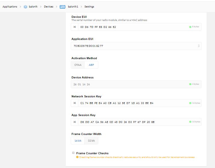
I have that. I have the aplication. I have the device EUI consisting of the MAC adress which came in the box with the 32u4. I have the activation method set to ABP. I have the frame counter width set to 16 bits. I have disabled the frame counter checks. I have copy-pasted the credentials into my code. I have it set up.
Hmm, I thought I would see a blue triangle and some data on the console if it’s working.
My idea would be to try and contact someone from the local community, maybe even the gateway owner close to you.
All TTN’ers are nice guys ( ) So maybe a community member could help you test your node.
Just send them a PM… its worth a try
So, for LMIC the wire to pin 6 (or another pin of your choice) is needed to detect a RxTimeout; without it, LMIC will probably hang after an uplink, when it’s trying to determine if there’s any downlink in RX1 or RX2.
I’d guess TinyLoRa does not support downlinks at all?
So, (very) long story short: when using LMIC on the 32u4 I’d say you’ll need the jumper wire as well. (But I’ve not used the Adafruit boards, nor TinyLoRa.)
“Privilege” doesn’t seem to be the correct translation for what you’re trying to say, but when far away from the gateway, indeed use SF12, which is the slowest transmission speed with the best range. Using SF12 the transmission will take a lot longer (so you can send far fewer packets per hour) but chances that a gateway receives the transmission are better. When SF12 works, go down to SF11 and so on.
Also, as long as you’ve not received anything: put the device as high as possible, outside, to improve the chances of a gateway receiving the transmission. And check the length of your antenna wire.
So: do you know how to set the device to use SF12 for your first tests?
Still then: if possible, then LMIC is better, as OTAA is better than ABP, and LMIC supports ADR. But as OTAA needs a downlink for the Join Accept and as you don’t have access to any gateway logs, starting with ABP is better now. And the Adafruit tutorial looks great, so I’d say that starting with TinyLora (which only supports ABP) seems fine too.
That’s correct when using ABP.
Also correct for ABP; blue upward icons denote uplinks. (For OTAA, you’d first see orange and green icons for the Join Request and Join Accept, if all is well, where the green icon is only shown in the gateway’s Traffic page, which you cannot see.)
As an aside: Adafruit’s Decoder for a TTN Payload Format does not support negative values. If you ever get to that point, then see Negative Temperature - #3 by arjanvanb.
I am sure I am not alone. I live in EU, I successfully use a couple of Feather clones (the BSFrance version). However, I am using LMIC, not TinyLora that apparently does not allow downlinks. LMIC is large but it leaves sufficient room for a temperature sensor library, or GPS, and is used by a lot of people, so it is easier to find help. And jumper is needed.
Did you enable the correct region in the TinyLoRa library?
Yeah, I have that.
Thanks for clarifying the pinouts.
I’d guess TinyLoRa does not support downlinks at all?
That’s fine for me.
When SF12 works, go down to SF11 and so on.
I want to use the 32u4 inside of a high altitude balloon to send data. Therefore I suppose that I should keep the SF value as high as possible at all times.
So: do you know how to set the device to use SF12 for your first tests?
Like this? lora.setDatarate(SF12BW125);
Maybe using LMIC leaves not enough flash memory for other code and libraries, like to read some sensors.
That’s exactly what Adafruit says.
After reading this I think I’m going to stay with the TinyLoRa library.
Also, my code here:
#include <TinyLoRa.h> #include <SPI.h>
// Network Session Key (MSB)
uint8_t NwkSkey[16] = { 0xC1, 0x74, 0xBB, 0xFE, 0xE4, 0xA0, 0xCB, 0xA1, 0x12, 0x5E, 0xD7, 0x1D, 0xA1, 0x33, 0xBE, 0xB4 };
// Application Session Key (MSB)
uint8_t AppSkey[16] = { 0xD8, 0xDD, 0xA7, 0xCA, 0x56, 0xAE, 0x0D, 0x45, 0xD0, 0x36, 0xD3, 0x97, 0x67, 0xDF, 0x20, 0x8B };
// Device Address (MSB)
uint8_t DevAddr[4] = { 0x26, 0x01, 0x14, 0x24 };
// Data Packet to Send to TTN
unsigned char loraData[1] = {“f”};
// How many times data transfer should occur, in seconds
const unsigned int sendInterval = 5;
// Pinout for Feather 32u4 LoRa
TinyLoRa lora = TinyLoRa(7, 8);
void setup()
{
delay(2000);
Serial.begin(9600);
while (! Serial);
// Initialize pin LED_BUILTIN as an output
pinMode(LED_BUILTIN, OUTPUT);
// Initialize LoRa
Serial.print(“Starting LoRa…”);
// define channel to send data on
lora.setChannel(MULTI);
// set datarate
lora.setDatarate(SF12BW125);
if(!lora.begin())
{
Serial.println(“Failed”);
Serial.println(“Check your radio”);
while(true);
}
Serial.println(“OK”);
}
void loop()
{
Serial.println(“Sending LoRa Data…”);
lora.sendData(loraData, sizeof(loraData), lora.frameCounter);
Serial.print("Frame Counter: ");
Serial.println(lora.frameCounter);
lora.frameCounter++;
// blink LED to indicate packet sent
digitalWrite(LED_BUILTIN, HIGH);
delay(1000);
digitalWrite(LED_BUILTIN, LOW);
Serial.println(“delaying…”);
delay(sendInterval * 1000);
}
Just to be sure, so you changed it, right? So it’s:
//#define US902 ///< Used in USA, Canada and South America
#define EU863 ///< Used in Europe
Also, I don’t know how easily the Arduino IDE detects changes in libraries; you may want to do some full compilation.
Not related to your problems:
I’ve no idea. For outdoor gateways you’ll always have line of sight from the sky. (Though the antenna orientation might not be optimal?) Beware that the range might be quite far then, and that you’re using a radio spectrum shared with others. Many others when transmitting from a high location.
Also, with SF12 you cannot send every 5 seconds (or every 6 seconds, given the 1 second delay for the LED): even when doing the experiment for only an hour, a 2 bytes application payload only allows for 25 messages on SF12 on the TTN Fair Access Policy, and only one message every 2 minutes for the maximum duty cycle regulations. LMIC will enforce the latter but not the former. TinyLoRa does not enforce anything. Finally, a hardcoded SF11 or SF12 is not allowed. (But I assume it’s just an experiment, not something you’d be using on a regular basis?)
For the very same reasons: while testing your code from home, if SF12 works, I’d surely go down to try better data rates if possible.
Also, TinyLoRa always transmits at maximum power; I don’t know what that maximum is, and if it’s within EU limits. All said, when using TinyLoRa then one’s own code needs to ensure one plays nice in the shared radio network.
//#define US902 ///< Used in USA, Canada and South America #define EU863 ///< Used in Europe
Yeah, I have it like that.
Also, I don’t know how easily the Arduino IDE detects changes in libraries; you may want to do some full compilation.
I’m not sure what is full compilation. I just hit the compile button. I have the .h and .cpp files in the same folder as the sketch.
Beware that the range might be quite far then, and that you’re using a radio spectrum shared with others. Many others when transmitting from a high location.
Yeah, someone said that he got 450km range with LoRa from 31km height.
But what if SF10 won’t be enough? Is there a way to change the SF value automatically? The thing has to work because once in the air, I can not reupload the code.
But I assume it’s just an experiment, not something you’d be using on a regular basis?
Well, I’m launching the balloon just once, but that can stay in the air and try to send the data for up to a couple of weeks so it will be sending many packets.
All said, when using TinyLoRa then one’s own code needs to ensure one plays nice in the shared radio network.
I’m fine with it sending data every hour or even once in a day. The tracker is for a contest, winner is the one which lasts longest. I really don’t care about the data, we just need to know if the tracker is still alive.
Hi everyone,
Thanks to your support, I got it working. Now I have it working using the “MCCl LoRaWAN LMIC” library and with a jumper.
Now I’m rushing to complete the tracker because the contest is in four days.
I’ve got a problem. I’m trying to encode a float into the message. I’m using the “ttn-abp-feather-us915-dht22”. There is a unknown command on the line 195. It’s “LMIC_f2sflt16(input);”. The compiler complains about it. When I googled it, it gave me like 7 results. Everything else about the code is fine. Any ideas?
 ) So maybe a community member could help you test your node.