Full Arduino Mini LoraWAN below 1uA Sleep Mode

use one of these between your battery and arduino

the problem is mostly the lipo protection kicking in when you are transmitting and the voltage dropped below protection value and shuts the power off shortly.
then after some time the voltage rise and it will reboot/transmit… or not and it gets in a loop.
so my suggestion is set bod to 1v8 and use a dc/dc step up/down… :slight_smile:

Unfortunately efficiency of many step up converters and step down converters in practice is not very good.
I have done some tests last year but don’t have the results at hand.
I do remember that step down converter efficiency dropped substantially when Vin neared Vout 3.3V for the switching models that use external coils (and is of course dependant on the converter model).
A good efficient LDO voltage regulator will be better (but will only step down).

Switching converters also have a higher quiescent current than a good LDO regulator which is less suitable for low-power applications.

I’d recommend to use a stepdown instead a LDO. One like TPS62740 which has 360nA Quiescent Current.

@lex_ph2lb
Thanks for this very interesting debugging, I think your battery is just crappy, what model are you using ?
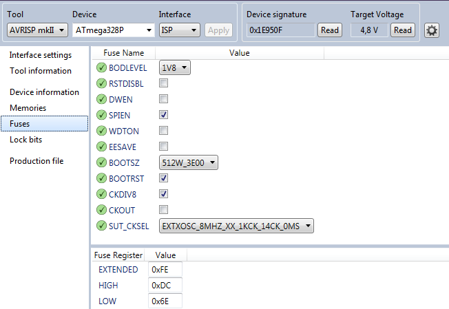
I always program bootloader with Atmel Studio (because I see exactly what is programmed in term of fuses ) Check picture below (but don’t use these settings, they are specific to ULPNode)

image

I’m using with a real AVRISP V2 programmer, trust me, price worth it

See more here about bootloader

6 Likes

@lex_ph2lb good research! thanks!

1 Like

I use the Saft LS14500 Lithium Thionyl Chloride AA Battery. Which I first bought at RS-Online (link to 201-9438).

After that I bought a batch at accu.nl (link to product). All the nodes who have problems use batteries from that batch.

Thanks for sharing the picture and the link to you’re page. I’m going to take a look at that.

Edit : @BoRRoZ, @bluejedi, @moeterbln, interesting idea’s. Worth trying a few experiments with them.

hummm, I got the same from RS also, need to try them, but 7.5€ the battery, should works, since you measured 3.3V and battery says 3.6V would be interesting to know at what voltage these batteies are considered as off for “safe operating mode” :wink:

Your battery read 3.3V with no consuption, so regarding datasheet, you’re close to the limit and your battery near empty. A fresh new one should be at least 3.5V :wink:

image

May be not lighting any LED and stop sensors during transmit could save you few mA of peak current, another tips could be to add 100uF/470uF capacitor between 3V3 and GND as reserve for peak current :wink:

2 Likes

360 nA that’s a very low quiescent current.

I have looked at these SPX3819 LDO regulators (I made some adapters to use them on a breadboard but have not tested them in practice yet).

It all comes down to the overall efficiency in practical real use, which is difficult to obtain from a datasheet.

Have a few spares from the first and second batch, so it’s hobby time this evening. :grinning:

Another solution for low-power applications are Lithium Iron Phosphate (LiFePO4 or LFP) cells.

Also see: Battery University Types of Li-Ion Batteries and their properties.

Advantages:

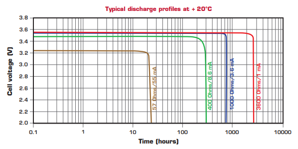
  • Nominal voltage is 3.2V which eliminates the need for voltage regulation circuitry for 3.3V equipment.
  • LFP batteries have a very constant discharge voltage.Voltage stays close to 3.2 V during discharge until the cell is exhausted. This allows the cell to deliver virtually full power until it is discharged.
  • The battery chemistry is much safer (and more forgiving) than regular 3.7V Lithium-Ion and Lithium-Polymer solutions which can catch fire when used/handled inappropriately.
  • LFP has higher current or peak-power ratings than LiCoO2.
  • LFP chemistry offers a longer cycle life than other Lithium-Ion approaches.

Disadvantages:

  • Lower energy density than regular Lithium-Ion and Lithium-Polymer (14% less than LiCo2).
  • Needs charger with lower voltage than regular Li-Ion and LiPo.
7 Likes

Hi guys,
sorry for the stupid question: the mappings for Charles MiniLora PCB V1.1 (based on the mappings in the github) must the following (I assumed):

.nss = 10
.rst = 0
.rxtx = LMIC_UNUSED_PIN
.dio = {2,7,8}

when I used this mappings I get a failure:
Arduino/libraries/arduino-lmic-master/src/lmic/radio.c:689

which sounds for me, that the pin mapping is wrong.

Any help is appreciated !

hi peter
I’m using

// Pin mapping for ch2i , charles board
const lmic_pinmap lmic_pins = {
    .nss = 10,
    .rxtx = LMIC_UNUSED_PIN,
    .rst = A0,
    .dio = {2, 7, 8},         // Specify pin numbers for DIO0, 1, 2
};

Thanks ursm,

I used yours, but the failure still continues.
(FAILURE
…/Arduino/libraries/arduino-lmic-master/src/lmic/radio.c:689)

I will try tomorrow with another board to exclude wrong soldering or whatever.

Happy about any ideas to track the error. (and solve :-))

Br Peter

Hi ursm,
checked with two other boards and it runs. So the pin setting is correct. The only thing I am missing now is - the RGB LED is doing nothing.
Thanks for your help !
Peter

1 Like

you have to do a little programming for them

Hi, I need help - my pro mini setup uses 5-10ma in sleep mode with the Lowpower lib, and I don’t know why.
Maybe someone spots an error

This is my setup:

Arduino Pro Mini (without LED) 8mhz/3.3v
Directly connected RFM95

Controlled through transistor (Pin 7 in the sketch)
Voltage Regulator + Level Converter + HC-SR04

This is the sketch:


Does anyone see a problem here?

What do you get when you disconnect the HC-SR04?
You need to find out what is still powered when you think its in sleep mode.

It is a process of eliminating components then either updating the software or changing hardware components for lower powered versions.

Andrew

1 Like

@tkerby, i tried your code this evening. for some reason no packets were send after sleep.

LMIC.opmode = OP_SHUTDOWN;
do_sleep(TX_INTERVAL);
LMIC.opmode = OP_NONE;
os_setCallback(&sendjob, do_send);

setting LMIC.opmode to OP_NONE after sleep made things working.
I didn’t dig to deep into LMIC, so I am not 100% sure why it seemed to work for others.

EDIT: doing so prevents channel cycling… now, I don’t change the opmode at all. doesn’t seem to affect power consumption. need to dig into lmic.

Michael

Not looked at the code, but a lot of Pro Minis would need to be modified for low current operation.

her some current usage numbers for a Mini Pro board (3V3 / 8MHz)

   variant               LED13 on   LED13 off     sleep 
unmodified                13mA       11mA
PWR LED removed            6mA        4mA         67uA
PWR LED & LDO rem.         4.6mA      3.3mA        4.2uA
1 Like