Hi! I’m pretty new to LoraWAN but made an attempt to build a sensor for my letterbox.
- I’ve bought and installed a public gateway (Mikrotik LR8)
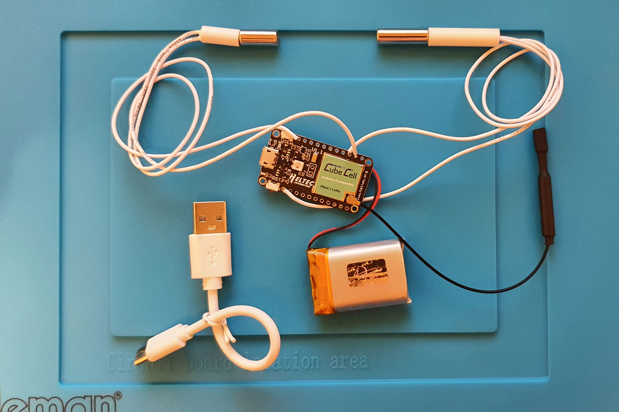
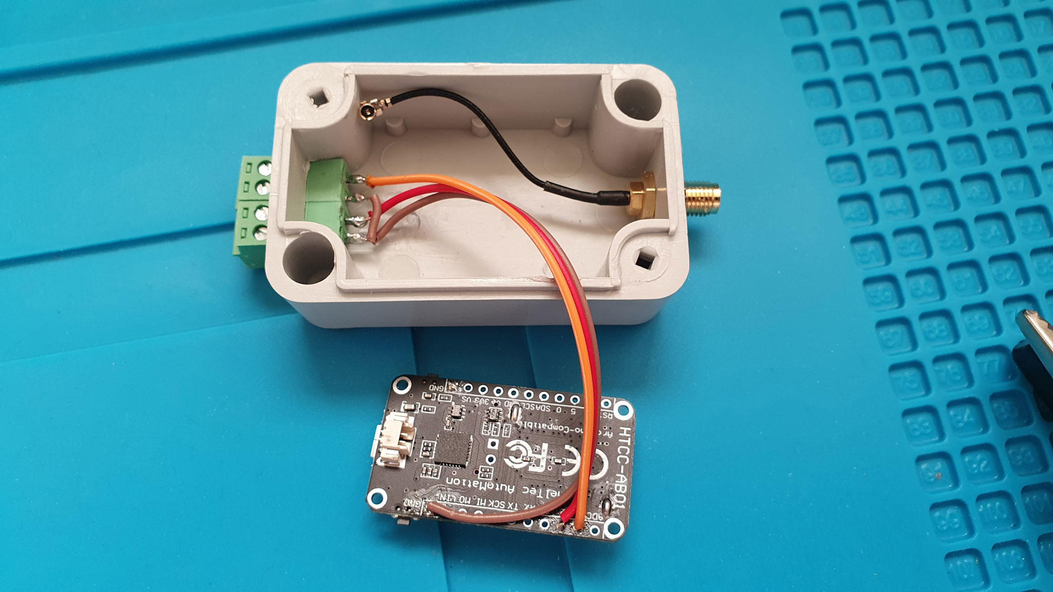
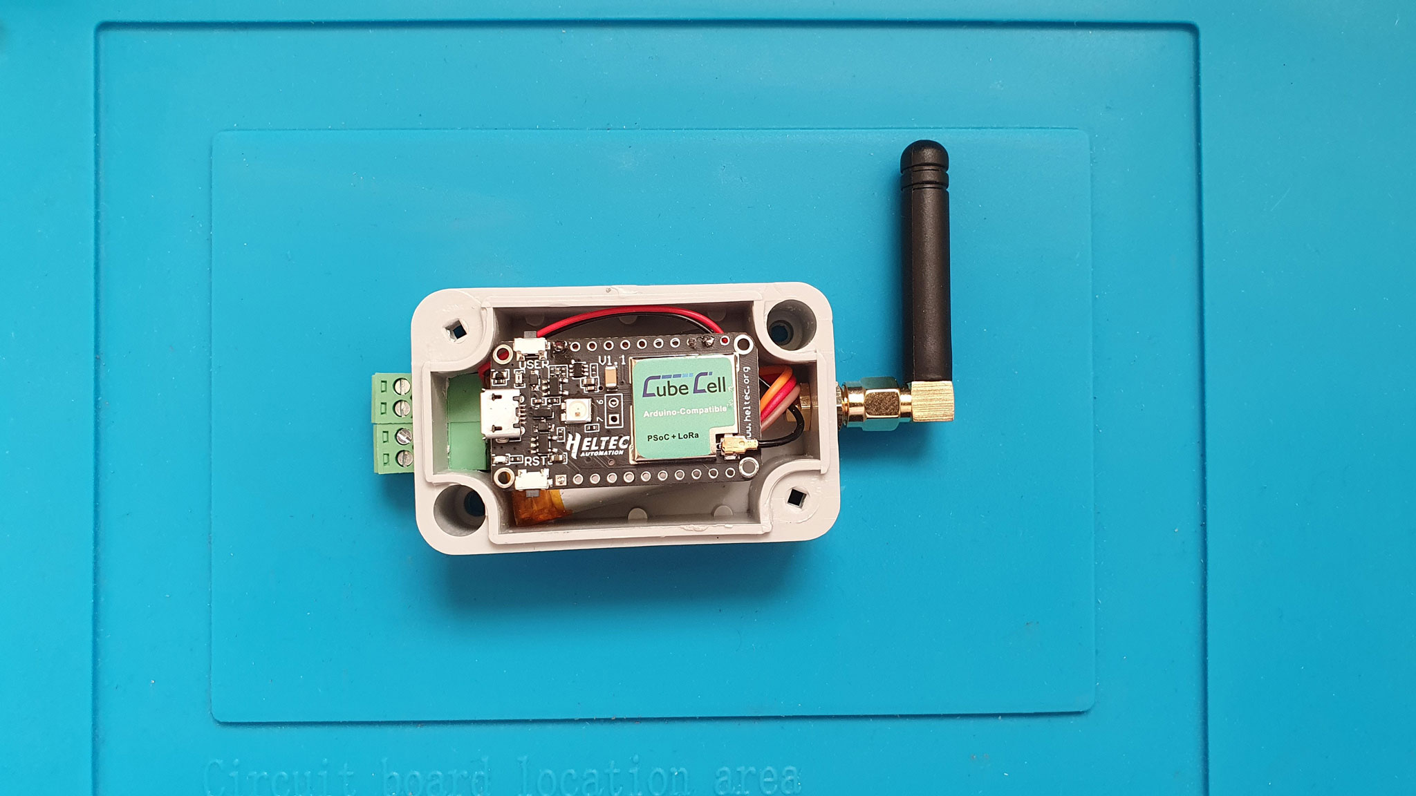
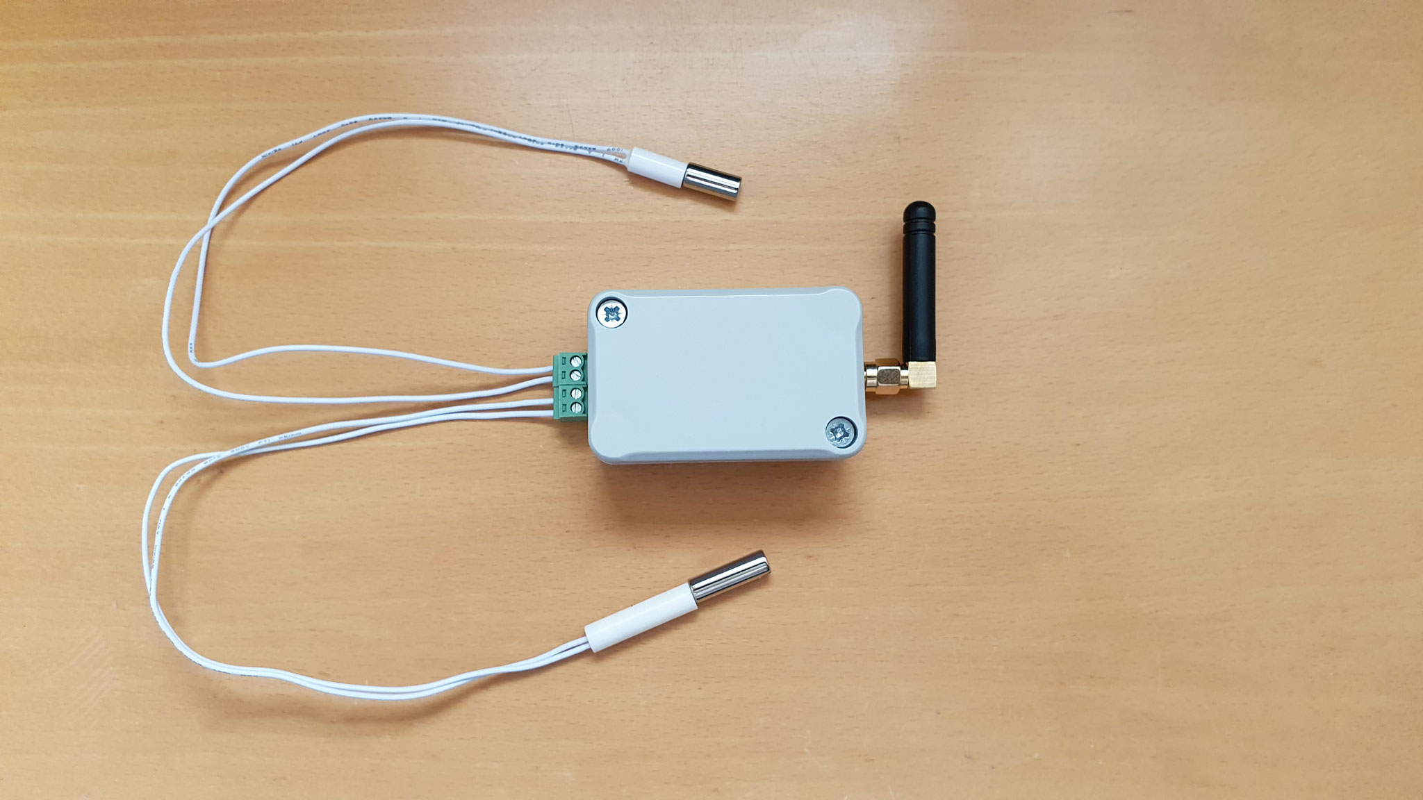
- I’ve bought HTCC-AB01 dev board, two reed switches and a 1000mAh LiPo battery. This is my rig:
I’m not a programmer at all, but out of available examples I somehow managed to develop the code in Arduino IDE that:
- successfully connects AB01 to TTN
- publishes battery voltage/level and states of two reed switches to TTN, in a one hour intervals
- publishes reed switch rising change (to state open) every time it’s opened
As this is intended to be used in the mailbox, reed sensor would be used once per day at most.
Here’s my code:
#include "LoRaWan_APP.h"
#include "Arduino.h"

/*
 * set LoraWan_RGB to Active,the RGB active in loraWan
 * RGB red means sending;
 * RGB purple means joined done;
 * RGB blue means RxWindow1;
 * RGB yellow means RxWindow2;
 * RGB green means received done;
 */

/* OTAA para*/
uint8_t devEui[] = { 0x22, 0x32, 0x33, 0x00, 0x00, 0x88, 0x88, 0x02 };
uint8_t appEui[] = { 0x32, 0x22, 0x00, 0x00, 0x88, 0x00, 0x88, 0x00 };
uint8_t appKey[] = { 0x88, 0x88, 0x88, 0x88, 0x88, 0x88, 0x88, 0x88, 0x88, 0x88, 0x88, 0x88, 0x88, 0x88, 0x66, 0x01 };

/* ABP para*/
uint8_t nwkSKey[] = { 0x15, 0xb1, 0xd0, 0xef, 0xa4, 0x63, 0xdf, 0xbe, 0x3d, 0x11, 0x18, 0x1e, 0x1e, 0xc7, 0xda,0x85 };
uint8_t appSKey[] = { 0xd7, 0x2c, 0x78, 0x75, 0x8c, 0xdc, 0xca, 0xbf, 0x55, 0xee, 0x4a, 0x77, 0x8d, 0x16, 0xef,0x67 };
uint32_t devAddr =  ( uint32_t )0x007e6ae1;

/*LoraWan channelsmask, default channels 0-7*/
uint16_t userChannelsMask[6]={ 0x00FF,0x0000,0x0000,0x0000,0x0000,0x0000 };

/*LoraWan region, select in arduino IDE tools*/
LoRaMacRegion_t loraWanRegion = ACTIVE_REGION;

/*LoraWan Class, Class A and Class C are supported*/
DeviceClass_t  loraWanClass = LORAWAN_CLASS;

/*the application data transmission duty cycle.  value in [ms].*/
uint32_t appTxDutyCycle = 60 * 60 * 1000;

/*OTAA or ABP*/
bool overTheAirActivation = LORAWAN_NETMODE;

/*ADR enable*/
bool loraWanAdr = LORAWAN_ADR;

/* set LORAWAN_Net_Reserve ON, the node could save the network info to flash, when node reset not need to join again */
bool keepNet = LORAWAN_NET_RESERVE;

/* Indicates if the node is sending confirmed or unconfirmed messages */
bool isTxConfirmed = LORAWAN_UPLINKMODE;

/* Application port */
uint8_t appPort = 2;

/*!
* Number of trials to transmit the frame, if the LoRaMAC layer did not
* receive an acknowledgment. The MAC performs a datarate adaptation,
* according to the LoRaWAN Specification V1.0.2, chapter 18.4, according
* to the following table:
*
* Transmission nb | Data Rate
* ----------------|-----------
* 1 (first)       | DR
* 2               | DR
* 3               | max(DR-1,0)
* 4               | max(DR-1,0)
* 5               | max(DR-2,0)
* 6               | max(DR-2,0)
* 7               | max(DR-3,0)
* 8               | max(DR-3,0)
*
* Note, that if NbTrials is set to 1 or 2, the MAC will not decrease
* the datarate, in case the LoRaMAC layer did not receive an acknowledgment
*/
uint8_t confirmedNbTrials = 4;

const int sensor1Pin = GPIO1;
const int sensor2Pin = GPIO2;
bool accelWoke = false;

int mapBatteryVoltageToLevel(int x, int in_min, int in_max, int out_min, int out_max) {
  return (x - in_min) * (out_max - out_min) / (in_max - in_min) + out_min;
}

/* Prepares the payload of the frame */
static bool prepareTxFrame(uint8_t port) {

  /*appData size is LORAWAN_APP_DATA_MAX_SIZE which is defined in "commissioning.h".
  *appDataSize max value is LORAWAN_APP_DATA_MAX_SIZE.
  *if enabled AT, don't modify LORAWAN_APP_DATA_MAX_SIZE, it may cause system hanging or failure.
  *if disabled AT, LORAWAN_APP_DATA_MAX_SIZE can be modified, the max value is reference to lorawan region and SF.
  *for example, if use REGION_CN470,
  *the max value for different DR can be found in MaxPayloadOfDatarateCN470 refer to DataratesCN470 and BandwidthsCN470 in "RegionCN470.h".
  */

  uint8_t sensor1PinState = digitalRead(sensor1Pin);
  uint8_t sensor2PinState = digitalRead(sensor2Pin);
  uint16_t batteryVoltage = getBatteryVoltage();
  uint8_t batteryLevel = mapBatteryVoltageToLevel(batteryVoltage, 3600, 4200, 0, 100);
  appDataSize = 5;
  appData[0] = sensor1PinState;
  appData[1] = sensor2PinState;
  appData[2] = highByte(batteryVoltage);
  appData[3] = highByte(batteryVoltage);
  appData[4] = batteryLevel;
  //Serial.print(F("Battery Voltage: "));
  //Serial.println(batteryVoltage);
  //Serial.print(F("Battery Level: "));
  //Serial.println(batteryLevel);
}

void accelWakeup() {
  delay(10);
  if (digitalRead(sensor1Pin) == HIGH || digitalRead(sensor2Pin) == HIGH) {
    accelWoke = true;
    Serial.println("accel woke");
  }
}

void setup() {
	Serial.begin(115200);

  pinMode(sensor1Pin, INPUT_PULLUP);
  pinMode(sensor2Pin, INPUT_PULLUP);

#if(AT_SUPPORT)
	enableAt();
#endif
	deviceState = DEVICE_STATE_INIT;
	LoRaWAN.ifskipjoin();

  accelWoke = false;
  attachInterrupt(sensor1Pin,accelWakeup,RISING);
  attachInterrupt(sensor2Pin,accelWakeup,RISING);

}

void loop() {

  switch(deviceState) {
    case DEVICE_STATE_INIT:
    {
#if(LORAWAN_DEVEUI_AUTO)
      LoRaWAN.generateDeveuiByChipID();
#endif
#if(AT_SUPPORT)
      getDevParam();
#endif
      printDevParam();
      LoRaWAN.init(loraWanClass,loraWanRegion);
      deviceState = DEVICE_STATE_JOIN;
      break;
    }
    case DEVICE_STATE_JOIN:
    {
      LoRaWAN.join();
      break;
    }
    case DEVICE_STATE_SEND:
    {
      prepareTxFrame(appPort);
      LoRaWAN.send();
      deviceState = DEVICE_STATE_CYCLE;
      break;
    }
    case DEVICE_STATE_CYCLE:
    {
      // Schedule next packet transmission
      txDutyCycleTime = appTxDutyCycle + randr( 0, APP_TX_DUTYCYCLE_RND );
      LoRaWAN.cycle(txDutyCycleTime);
      deviceState = DEVICE_STATE_SLEEP;
      break;
    }
    case DEVICE_STATE_SLEEP:
    {
      if (accelWoke) {
        if (IsLoRaMacNetworkJoined) {

          Serial.print("sensor1Pin: ");
          Serial.println(digitalRead(sensor1Pin));
          Serial.print("sensor2Pin: ");
          Serial.println(digitalRead(sensor2Pin));
          Serial.println("Transmitting LoRaWAN");
          prepareTxFrame(appPort);
          LoRaWAN.send();

          delay(120000);
          while (digitalRead(sensor1Pin) == HIGH || digitalRead(sensor1Pin) == HIGH) {
            delay(100);
          }
          delay(1000);

          Serial.print("sensor1Pin: ");
          Serial.println(digitalRead(sensor1Pin));
          Serial.print("sensor2Pin: ");
          Serial.println(digitalRead(sensor2Pin));
          Serial.println("Transmitting LoRaWAN");
          prepareTxFrame(appPort);
          LoRaWAN.send();

        }
        accelWoke = false;
        Serial.println("accel put to sleep");
      }
      LoRaWAN.sleep();
      break;
    }
    default:
    {
      deviceState = DEVICE_STATE_INIT;
      break;
    }
  }
}
I’m facing two issues, though:
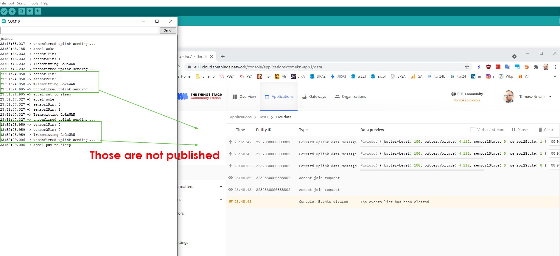
- Although every reed switch open (PIN change from 0 to 1) is published to TTN, I never see reed switch close (PIN change from 1 to 0) published. I suspect it’s because of transmission interval limitations, but I’ve tried postponing the second transmission by 40 and even 120 seconds - still not seeing it published in the app LiveView. Any ideas why that happens?
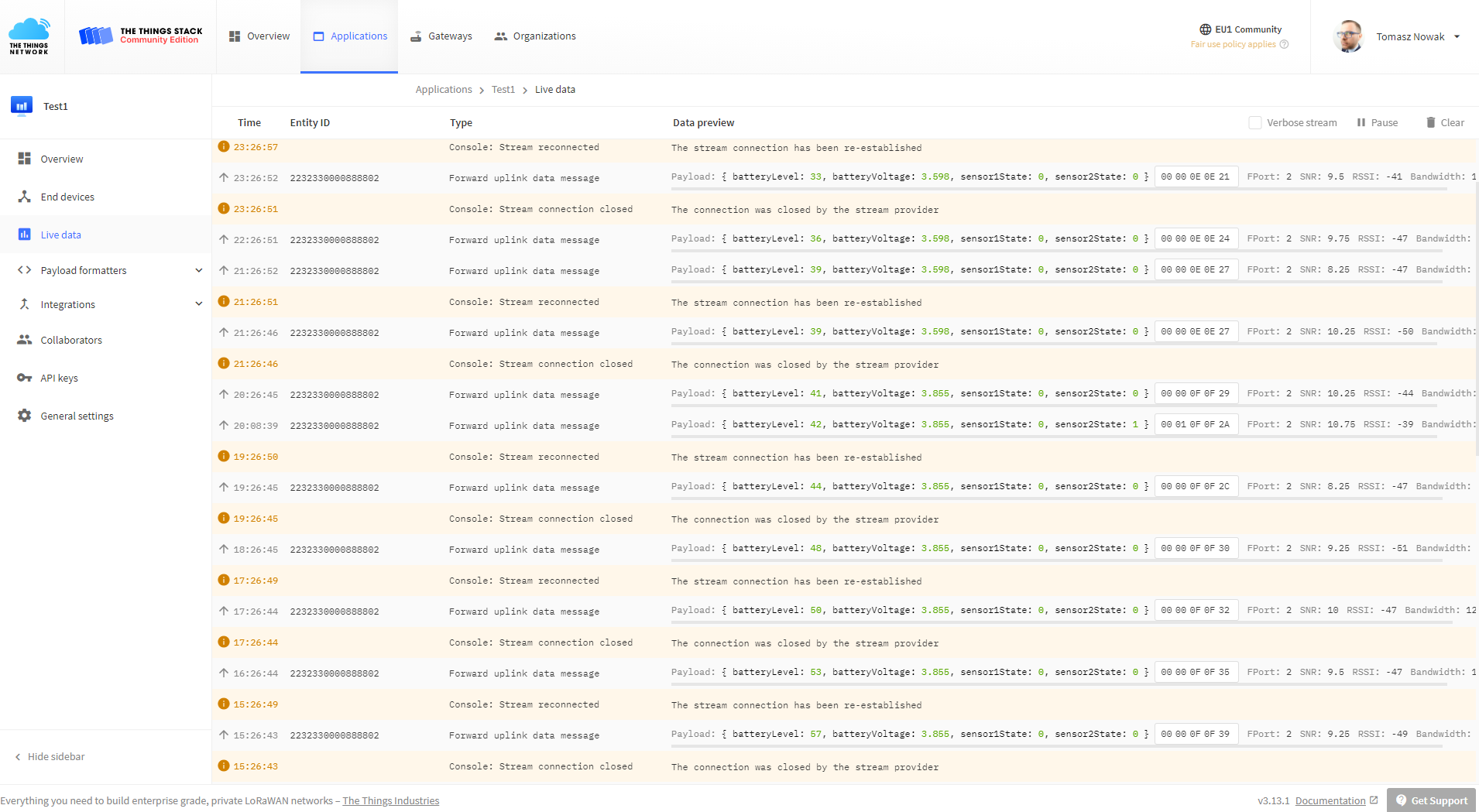
- Second issue: as the code (based on examples) seems to put the device to sleep mode after each transmission, I was hoping to get at least several weeks (or even months) of battery life. Unfortunately, my battery has been drained in only one day (with only 1 transmission every hour). Why is that? Please see battery voltage/level on that screenshot:

 But Device Live View still doesn’t show it