HI!
I have tried to change SF from SF7BW125 to SF12BW125, but I don’t know how. Check my TTN console screenshoot .
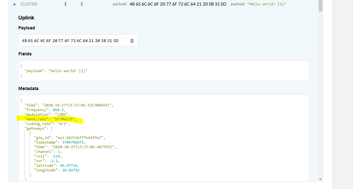
PS: I used a IMST gateway
HI!
I have tried to change SF from SF7BW125 to SF12BW125, but I don’t know how. Check my TTN console screenshoot .
PS: I used a IMST gateway
Why do you want to? Your message would take 32 times longer to transmit, which means more drain on your node battery and more time when you are using the frequency that it’s not available to someone else.
Please don’t use such an excessively high spreading factor where it is not needed.
And please don’t send long ascii text payloads either.
Besides, your question isn’t even answerable since you’ve given no information about your node.
What are you using, and what goal are you trying to accomplish?
I use this setup for my end-device (node) node link
I want to achieve maximum tx power and the largest range between node and gateway
Please don’t, that’s not really compatible with the TTN usage guidelines.
You should use only what is actually needed, your uplink report shows that your current settings are sufficient, if you made it change it should only be to SF8 or at most 9.
And please stop sending “Hello World” payloads, that’s just wasting network capacity to no benefit.
You’re building a single channel “gateway”. Such a gateway is not LoRaWAN compliant and is not the kind of gateway that TTN likes to see on its network (AFAIK). In a sense it is contrary to some TTN principles, especially combined with the wish for “maximum tx power”.
You’ll find that people here will be very reluctant to help you with this.
Please try to understand the limits of LoRaWAN and how to “play nice” and you can get a lot of useful advice here. Gateways supporting the full 8 LoRa channels are no longer really expensive and it would help TTN if you use a compliant gateway.
Also be aware that by ‘forcing’ the packet to SF12, you are significantly limiting the number of packets you can send per day, to around 22 packets a day in this case.
Hard coded SF12 is not allowed on the network as per Lora Alliance recommendations.
While the linked instructions include such, the asker said they have an IMST gateway, so hopefully they are using only the node part of those instructions.
Though if intended to work with a single-channel abomination, it probably is using only a single uplink frequency, which is a mistake. And beside that I’d be rather wary of any copy of LMiC last updated 5 years ago anyway.
Really the asker needs to start by explaining a clear goal for what they want to do, then finding a suitable node
Hi,
I installed an IMST gateway in atic of our company building, located in Romania, East, closed to Ukraine border (25km). I do this for community, not for profit. I also would like to learn more about this technology. Hence, the long time it took to install it. But I have met problems with the range of LORA radio:
1.a) I use this LORA Lite Gateway (https://shop.imst.de/wireless-modules/lora-products/36/lite-gateway-demonstration-platform-for-lora-technology) that is based on iC880A - “is able to receive packets of different end devices send with different spreading factors on up to 8 channels in parallel.”
(https://shop.imst.de/wireless-modules/lora-products/8/ic880a-spi-lorawan-concentrator-868-mhz?number=404802)
1.b) with this 8dBi LPRS-ANT-868-DP-N-F antena (http://www.farnell.com/datasheets/2549160.pdf?_ga=2.45256548.1761733434.1589816682-996021991.1589816682);
I have this device located in attic of the building and antenna is just over the roof (at about 8m above ground). Is one of the tallest building nearby our residential area.
For testing, I use this LORA device to send data through the Lite Gateway: https://www.seeedstudio.com/Raspberry-Pi-LoRa-GPS-HAT-support-868M-frequency.html
The gateway was registered in TTN and here are the results: I can get traffic data when the RPI-Lora device is about 20m around the building or in the building.
When I go further (200m for instance) => there’s no traffic in ttn-console nor in the linux shell of the Lite-Gateway.
When asked for support at imst.de, they suggested: “The screenshots show the information of some uplinks sent with SF7BW125. We would recommend you to use SF12BW125 and the maximum tx power to achieve the largest range.”
Could you tell me why this happens, how to investigate deeper, or how can we fix it, please?
On the other hand, please let me know if this iC880A is not suitable for LORAWAN/TTN, but I’ve tried to invest in a good gateway.
Thanks,
M.
Can we assume you have done the usual install troubleshooting wrt ant connection…
Check connection tight (tooled not fingers!), correct connectors & couplers…male/female/polarity (often folk find they have used e.g. female to female with no direct centre conductor contact yielding just poor capacitive coupling!), use of very low loss cable for runs >1-2m, no kinks or sharp bends below cable mbr, no cable breaks or wire whiskers causing shorts…etc?
Also have you operated GW at ALL times with an ant/load connected, as to do otherwise risks frying the rf front end of GW leading to such loss of sensitivity,etc. Don’t be tempted even for a quick bench power up test 
Also, is it a known good node (same rules on operation with ant connected only  )… tested against another GW in your area?
Not being funny, but it’s worth checking the LoRa antenna is screwed in to the correct antenna socket - the SeedStudio picture has the antenna screwed in to the GPS …
What software are you using on the Pi to run the HAT? This is the software to set an initial SF/DR but please be aware running devices are not quite as simple as going for SF12 & max power as you’d run the risk of saturating the area with long running transmissions.
Either way, SF7 should work line of sight for a good few hundred meters so there is definitely more going on than just changing the rate & power.
Then as others suggested, you really need to investigate why you have such very short range.
Although the Pi will create a degree of EMI that can reduce range, if the Pi node can see the gateway antenna when outside, then you would expect a good deal more than 200m range.
The solution to your problem is very unlikley to be to switch to SF12.
I remember that I had issues with antenna connectivity in the beginning: had female-to-female connector without centre conductor! I think it did run for a day or so till I’ve found this issue, I think I could also had a short between centre/ground antenna-connector when I tried to use a small copper centre wire from a RG6 cable. This case I had, I think for a few minutes till I found that has no effect and hence, decided to wait till I’ve got the proper cable adapter.
Would any of these action damage the RF front-end of the gateway?
How can I test?
In addition to a simple digital-meter, I have acces to a spectrum-analyser DSA875. Though I’ve never used, I can try to learn using it to find out if the rf-frontend is fried, or if the antenna is not properly wired?
If you know practical hints how to test, or where can I read about this, let me know.
Thanks,
M.
It’s usually pretty bad luck to fry the radio due to lack of antenna - it’s more often extended transmissions that will hurt the output stage. So I’d travel hopeful.
The first thing is to get a simple stick / helical coil antenna that has the right gender/connection on to both the gateway and the device where you can feel you’ve got it on good & firm. If the gateway is at a window, go for a walk (not ideal with a Pi based device, but c’est la vie) with the device trying to keep in sight of the window.
In some random ideal world, you have another device of a different make / MCU with perhaps a different antenna for testing with.
As for resistances on the various cables, I’ll let @LoRaTracker comment, he’s far more knowledgeable at RF.
The iMST GW will happily run off a USB power bank (you will need to hack a USB cable to the barrel connector. Directly attach the Ant that came with the GW and take the node with another power bank and ant attached and take with a 3G/4G dongle to enable the GW to connect to the net to TTN back end/console. Head to a nearby field or park, fire all up and see what happens…you can check rssi/snr in Console and see how all behaving If it’s bad you will soon find out [I use similar config when doing client coverage tests/what if checks and surveys and works simply & well… have iPad or small notebook to keep watching console whilst tether to my mobile phone when out and about for quick feedback…]
I have to look them up.
Myself I would put a 50R terminator where the antenna was and meassure the resitance that way, you would expect it to be fairly close to 50R.
I have a 8M length of super low loss stuff, Ecoflex 10 plus with N Type connectors, that I use for connecting an the external antenna.
I measured a 50R teminator, put it on one end with an adapter and it measured 0.8ohm more from the other end, so 0.1ohm per metre.
Beware the USB powerbanks are often horribly noisy well into the radio spectrum.
LoRa is a fairly noise-immune modulation, but it isn’t perfect. I’ve seen simpler OOK systems rendered extremely short range by the noise of trying to run them on a powerbank, and when a LoRa signal gets marginal enough it would ultimately be an issue there too.
Of course that has little to do with the original problem, just cautioning it as something to keep in mind during such a test.
Thank you all for the suggestions.
But:
my top-roof antenna has an extender cable of 1m only. Unfortunately, I cannot take off the antenna and have no access to take the extender cable out. But both were new, fresh installed and I only wanted to test that signal goes through the antenna ok.
I am thinking to use a spectrum analyser with a small antenna that I can measure the radiated wave of 868Mhz: I connect the gateway to antenna, or disconnect it from big top-roof antenna and measure without antena. I could also compare with the small white antenna I have from PI-hat.
Our office is in a residential area where the radio is quite low. There’s no Lora around for 100km or so; just WiFi from neighbours. So I don’t think I need to go out … Or, else I don’t get the test Jeff proposed.
Imho I did a similar test using pi-hat LORA and IMST-GW (with antenna or without).
If you want to know what’s going on with your antenna and the attached cable you need a VNA (vector network analyser) or a similar instrument. e.g. AAI N1201SA. Then you can see most of the relevant rf-parameters of your antenna/cable and detect faults.
Indeed ![]() Its a well known and widely reported phenomenoma (not least here on the Forum over last few years) - when used in anger vs a quick dirty ‘have I fried my system check’ as outlined above, I typically use metal cased units vs plastic and then place an RF choke on the USB cable - itself 1-2m in length - close to the Powerbank output - to help limit inline coupling; just long enough to move GW away from immediate source but not so far as to cause voltage drop on the cable during consumption spikes (I select also USB banks that I know are at higher end of output voltage spec as found some low voltage will drop out if on too long a cable
Its a well known and widely reported phenomenoma (not least here on the Forum over last few years) - when used in anger vs a quick dirty ‘have I fried my system check’ as outlined above, I typically use metal cased units vs plastic and then place an RF choke on the USB cable - itself 1-2m in length - close to the Powerbank output - to help limit inline coupling; just long enough to move GW away from immediate source but not so far as to cause voltage drop on the cable during consumption spikes (I select also USB banks that I know are at higher end of output voltage spec as found some low voltage will drop out if on too long a cable ![]() )
)
Yep, better than most I would say - and better than what I call ‘legacy’ modulations as you call out such as OOK & FSK…that’s why I have been an evangelist for LoRa since long before the 1st production devices came to market in mid’13…indeed even before the formal announcement of the technology in late '12 ![]()
If used for the coverage tests outined in my post then the noise generated by the USB powerbank can be considered as potential real world extra headroom from the tests for any subsequent production deployment using lower voltage lower noise switching sources, not withstanding the fact that many of GW’s one can buy typically have a potentially noisy switching PSU/POL Sources built in anyhow ![]() - best not add too much more as noise is addative as you will well know…
- best not add too much more as noise is addative as you will well know…
And indeed that was the purpose of the post to help OP quickly determine if he had trashed either end of his system, or mis-configured, with the set up potentially highlighting if system still worked in ‘limp along’ mode but with much reduced sensitivity or link budget. Have seen devices operate quite well for many hours without any external ant (often done with early Semtech demo kit!) without harm but also seen units killed from just a couple of minutes of bench operation without ant - including a GW that was killed by several nodes in close proximity all asking for Join Accepts in qucik succession causing the GW to loose front end…limped along but with link budgets subseuently 25-50db below what was originally the case ![]()