I have code for this. Will send it to you @Aiden101.
a cloned TTN uno 
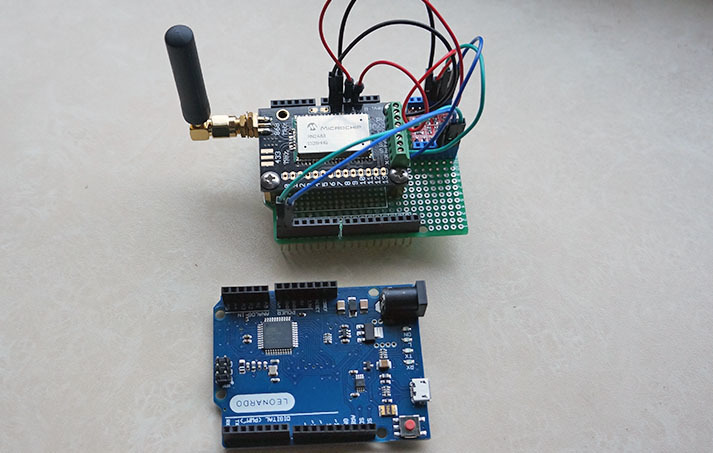
works with https://github.com/TheThingsNetwork/workshops
I used this leonardo board
and this level converter
1 Like
Wow !
Can I have your email to ask something about this ?
Best regard !
I used this tutorial to build my first ever lora node with a arduino nano and send some data over TTN, very cool! 
It works like a charm, but there’s one thing I was wondering though: the RN2483 works at 3.3v, I believe the rx/tx lines of the arduino nano work at 5v. Would this configuration not slowly cook the RN2483 ? should I add some level shifter, or should I swicth to a 3.3v arduino pro?
You should use a lever shifter for that (is good practice) of indeed switch to a Arduino Pro 3.3V
How to use the level shifters, check out the info on this link : https://www.tindie.com/products/DrAzzy/rn2483-breakout-bare-board/
1 Like
I recently bought a RN2483 and it gives a weird reply on the sys get hweui command.
In the reply, just before the readable HW-EUI (16 characters that represent the EUI in hex-format) there are 9 other characters that are not readable ascii-characters (resulting in garbage-characters just before the HW-EUI). The hex values of the garbage-characters are: C4 FE 04 60 1C 03 78 8D FF.
Manual check in a serial-terminal with an usb-to-serial module confirms that these leading garbage-characters are really produced by the RN2483-chip and not by any software bug.
This breaks the hweui-check and OTAA-procedure in the RN2483-Arduino-Library. I had to add the following line in rn2xx3.cpp directly after the line addr.trim() (in two places) to make the library work for OTAA:
if(addr.length() > 16) addr=String(addr.substring(addr.length()-16));
This line removes any garbage-characters that are replied before the real HW-EUI.
With this modification it is perfectly running the OTAA software
Does anyone has the same problem? Is this a v1.01 bug/feature or do I have a faulty chip?
(My RN2483-chip replies as version: version1.0.1 Dec 15 2015 09:38:09)
1 Like
I like your setup, where did you get that VeroBoard?
I ordered 2 of these… should work with the TTN firmware to … I’ll try 
- they arrived… but they don’t work with my arduino ide 1.8.1
1 Like
Hi everyone,
Can I send and receive data p2p using LoRa Shield RN2483 and Arduino uno? I just would like to approve the concept of node to node communication, Could you give me some tips and instructions about.
This has been discussed on this forum previously, use the search (or google) to find the information.
1 Like
Thank you Kersing for your reply.
Actually I have already search in the forum and google as well but I did not find anything related to the topic. I might not have a good experince for searching. Could you send a link to me please.
I’ve had this question before, so I decided to put an example on github:
4 Likes
Great, thank’s
Hello, i have made a node, using an Arduino and a RN2483_PICtail board, following this guide.
But i can only send a static message, and i would like to send data form ex. a compass module connected to my arduino.
How do i do that?
I’m using the code from [quote=“jpmeijers, post:1, topic:1574”]
Next on to the software side.Download the zip file containing the code from my github repository: https://github.com/jpmeijers/RN2483-Arduino-Library
[/quote]
thanks
Look at the example included with that library. specifically SodaqOne-TTN-Mapper-ascii and SodaqOne-TTN-Mapper-binary. These two read coordinates from a GPS and transmit them via the RN2483. With your compass it should be similar.
1 Like
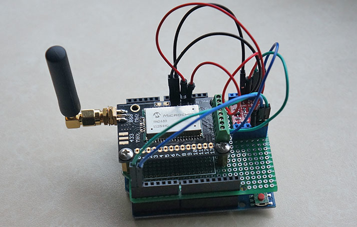
hi @jpmeijers , this dual face RN2483 / arduino nano PCB is still a great solution!
however:
- RN2483 cannot be run at 5 V, it shuts down the RF transmitter
- arduino nano should not be run at 3.3 V, unless you lower the operation frequency from 16 to 8 MHz (max 12 MHz @ 3.3V)
Are you using this @ 3.3V?
I would love to find a similar dual face RN2483 / arduino pro mini PCB !
The RN2483 is actually run at 3.3V from the 3.3V output on the Arduino Nano. So even if the Nano is running at 5V, there is a voltage regulator to output 3.3V from which you can feed the RN2483. The only problem you are left with is the voltage levels on the serial connection between the Nano and the RN which are too high. It however seems to work ok at 0-5V, but you might need to add a resistor in series to protect the RN2483.
If there is a deman for this board I can see if I can improve it slightly and make a new batch.
Hello,
Is it possible to program the node to send a binary message?
i want to send this byte:
1000 1010
but i can’t find out how to do it…
I tried to convert it to Ascii, but then i get " . ", and that translate back to “1010”
has anyone tried to controle the bit’s in the payload, to try and maximize the data send.?
Hi @jpmeijers,
Thanks for the knowledge.
Could you please let me know if this code works as on today (August 2017) as well.
I ask this as staging is obsolete now.
Eagerly,
Sid