kersing… nice that explains it …
now the sketch compiles properly
When I open the monitor I get …
startup
When using OTAA, register this DevEUI:
RN2483 version number:
So it looks like Serial.println(myLora.hweui());
is returning ‘NULL’…
then Serial.println(myLora.sysver());
returns NULL
Why are these values not being returned… ?
How can I test that my RN2483 setup is correct… ??
Maybe I have to test something about the RN2483 connection…
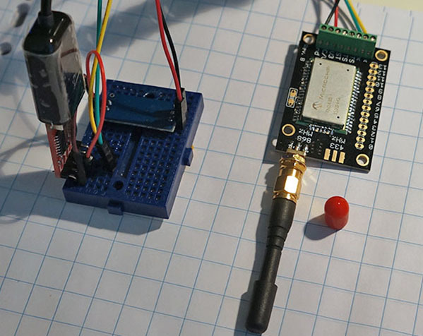
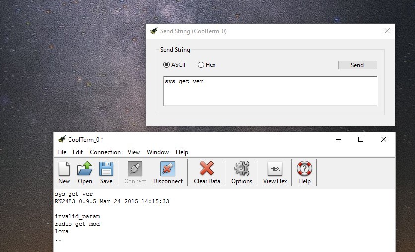
you have to connect your RN2483 in a way that you can send serial commands from your computer to the chip.
for that you will need a usb to serial interface , a 5 v to 3v3 converter for the power and a terminal program to communicate with the chip.
So far, I am reaching a range of around 300 meters, with my gateway outside and my node outside as well. This was in a ‘foresty area’.
Not too far, as I’m aiming at around 2km for my application. Will also place the antenna of my gateway on a higher location and see how much that helps.
I have been reading about ‘lowering the data rate’, but did not succeed in founding out yet how to do this . Any help?
Lowering the data rate means using a higher spreading factor (SF). If you’re testing for maximum coverage, try SF12 and see how far you get. But keep in mind that doing that, you are increasing the air time needed to transmit every message, which in turn means you get to send less messages a day.
Still, that’s good for testing.
The height at which your gateway is located makes a HUGE difference. An outdoors gateway at ground level will not give you more than a couple hundred meters of range, while the same gateway raised at least 5 meters above the ground will give you up to 10km in a rural area. The higher, the better.
Thanks for the feedback. The SF is already at 12, and I have now used ‘set pwr 14’ to get the power to +14dB.
The poweridx is already at 1, which should be the most powerfull.
What is the difference anyway between the ‘poweridx’ and ‘pwr’? By default the poweridx was set to most powerfull, but the ‘pwr’ not.
Problem is, I am not sure if it’s my gateway (and location) that is the limiting factor or my node, which uses a paperclip cut to the right size as an antenna.
My gateway is at around 5 meters above ground level. Perhaps I should try with a better antenna on the gateway (what do you think about this? https://www.conrad.nl/nl/868-mhz-antenne-ht250a-h-tronic-1618115-1618115-zendfrequentie-868-mhz-1273411.html
At least I could try to place the antenna further up and outside then.
Is it a single channel gateway?
If so I have noticed that it is very difficult to have it go past 300m range in an urban environment even with the antenna on the roof.
Anyone got better ranges with single channel already?
Thanks for this great post. It helped me (completely new to the subject) setting up a node with ABP (OTAA for some reasons does not work). The node needs a power interrupt as described here, but I can work around this issue. Unfortunately I am stuck at the following two steps:
I am using the TXfastViaTTN library by jpmeijers. With this library, is it possible to check if there is a gateway in range? (My upload messages only occasionally make it to the TTN dashboard and I need to isolate this problem)
With the same library, how can I receive downlink messages (and e.g. display it to the serial monitor?)
Can someone explain to me how this works without level-shifter?
I read the datasheets of the RN2483 and it says that the voltage on a port can not be higher than VDD + 0,3 and the digital ports on an arduino use 5V.
How is it even possible for this example to work??
You are absolutely correct about what the datasheet says. This is something that at the start I ignored and tried, and luckily it worked. I have been using the RN2483 at 5V logic levels with an Arduino Uno for more than a year now without any problems.
I interpret the datasheet’s maximum values as “maximum values at which the module will operate normally”. Focus on the “normally”. Indeed when you do it in this way the module does not operate 100% as specified. Specifically the power usage during sleep mode is much higher than what it should be because of leakage currents through the protection diodes on the input pins.
I hope this sort of answers your question. Maybe someone else has another idea about this.
Thanks for you answer, it completely answers my question
I’m trying out this LORA-project for myself and I have one more question,
does the module work without antenna and if so, do you have any idea of the range?
I really appreciate this post, thank you for posting it!
Exceeding them might well damage the unit, so proceed at your own risk… (keep in mind: past results are no guarantee of future performance)
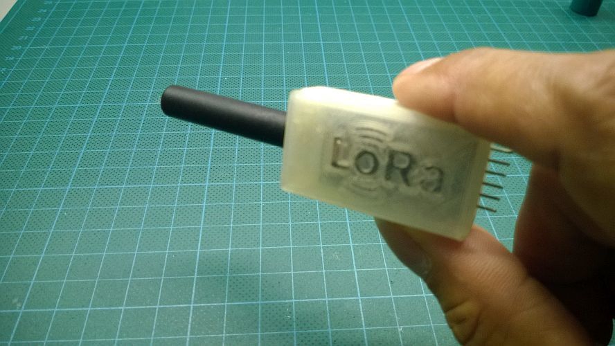
Running it without antenna might damage the module. Also range will be next to nothing (as in centimetres). Use a 82.2mm wire connected to the 868 output if you do not want to invest in a ‘real’ antenna
I’m trying to build a very simple setup using two Arduinos and two RN2483 chips.
I want to have one chip transmit and the other to receive, using LEDs to indicate when one is sending and the other one is receiving.
I’ve been looking through code online and i can’t find anything as basic as this.
I’m trying to learn the very basics of LoRa first before moving onto something more complex.
Does anyone know how I could do this? Or is anyone willing to help me with this please?