A loRa network consists of a gateway (in the middle, talking to a backend via a backhaul (eg internet)) and one or more nodes around it. Think of it as a star-shaped pattern.
One node does not known of the existence of the other, they cannot ‘speak’ to each other. They do share the same frequencies (to be precise 8 of them) so they could be talking at the same time on the same frequency. But you’d better see this as both of them shouting without listening
I seriously doubt if it’s possible to let one RN2483 think it’s a gateway as the chip has the LoRa stack built into itself. But maybe someone else, with more knowledge knows a way to get this done, legally. I know of the RFM modules (another chip) to be able to operate as a single channel gateway.
Yeah, I’ve built the single channel gateway setup using a raspberry pi already and it seems to work ok.
I was just hoping maybe someone had tried something as simple as this before.
By learn the basics, i mean learn the basics for how to use the RN2483 chip, to do this by just using the RN2483 chips to send and receive, and have the Arduino code light an LED, when it detects a signal being received and transmitted etc.
For the RN2483 the basics are LoRaWAN, not LoRa
You should be able to get two chips talking using radio commands, however examples on how to do this will be scarce. For LoRaWAN there are plenty examples and libraries.
Why is that hard to find? I’ve been looking for examples of just using the radio commands but have yet to find anything that I can use to make this work.
*Edit: I’ve just realised that this probably isn’t the right thread to post this on, so apologies for that!
I’m just trying to find a good tutorial on RN2483 point to point communication using an Arduino.
Because people buy these modules for LoRaWAN. If you want lora there are cheaper modules to be had. And LoRaWan takes just 5 lines of code with these, so why bother with less advanced comms requiring more code?
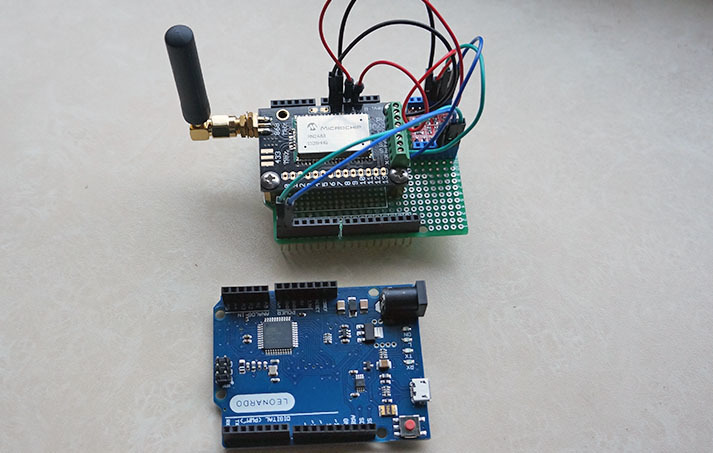
I used this tutorial to build my first ever lora node with a arduino nano and send some data over TTN, very cool!
It works like a charm, but there’s one thing I was wondering though: the RN2483 works at 3.3v, I believe the rx/tx lines of the arduino nano work at 5v. Would this configuration not slowly cook the RN2483 ? should I add some level shifter, or should I swicth to a 3.3v arduino pro?
I recently bought a RN2483 and it gives a weird reply on the sys get hweui command.
In the reply, just before the readable HW-EUI (16 characters that represent the EUI in hex-format) there are 9 other characters that are not readable ascii-characters (resulting in garbage-characters just before the HW-EUI). The hex values of the garbage-characters are: C4 FE 04 60 1C 03 78 8D FF.
Manual check in a serial-terminal with an usb-to-serial module confirms that these leading garbage-characters are really produced by the RN2483-chip and not by any software bug.
This breaks the hweui-check and OTAA-procedure in the RN2483-Arduino-Library. I had to add the following line in rn2xx3.cpp directly after the line addr.trim() (in two places) to make the library work for OTAA:
This line removes any garbage-characters that are replied before the real HW-EUI.
With this modification it is perfectly running the OTAA software
Does anyone has the same problem? Is this a v1.01 bug/feature or do I have a faulty chip?
(My RN2483-chip replies as version: version1.0.1 Dec 15 2015 09:38:09)
Hi everyone,
Can I send and receive data p2p using LoRa Shield RN2483 and Arduino uno? I just would like to approve the concept of node to node communication, Could you give me some tips and instructions about.
Thank you Kersing for your reply.
Actually I have already search in the forum and google as well but I did not find anything related to the topic. I might not have a good experince for searching. Could you send a link to me please.
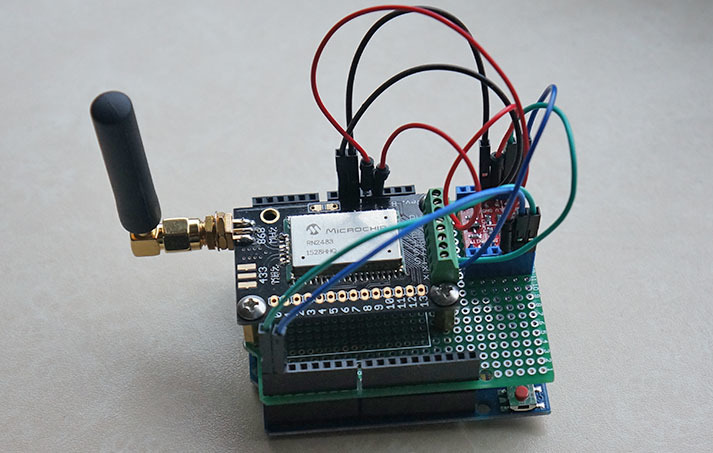
Hello, i have made a node, using an Arduino and a RN2483_PICtail board, following this guide.
But i can only send a static message, and i would like to send data form ex. a compass module connected to my arduino.
How do i do that?
I’m using the code from [quote=“jpmeijers, post:1, topic:1574”]
Next on to the software side.Download the zip file containing the code from my github repository: https://github.com/jpmeijers/RN2483-Arduino-Library
[/quote]
Look at the example included with that library. specifically SodaqOne-TTN-Mapper-ascii and SodaqOne-TTN-Mapper-binary. These two read coordinates from a GPS and transmit them via the RN2483. With your compass it should be similar.