This happens when the serial baud rate is not correct for some reason. Try to play around with it a bit. Serial.begin(9600) might work.
abpel: which type/clon of arduino do you use? means: what is the quarz frequency on it?
Do you use the correct type in the Board menu?
Some radio silence, but several steps forward:
I am now seeing the ‘TXing’ message in the serial monitor of my Arduino at baud rate 57600. So that seems to be working.
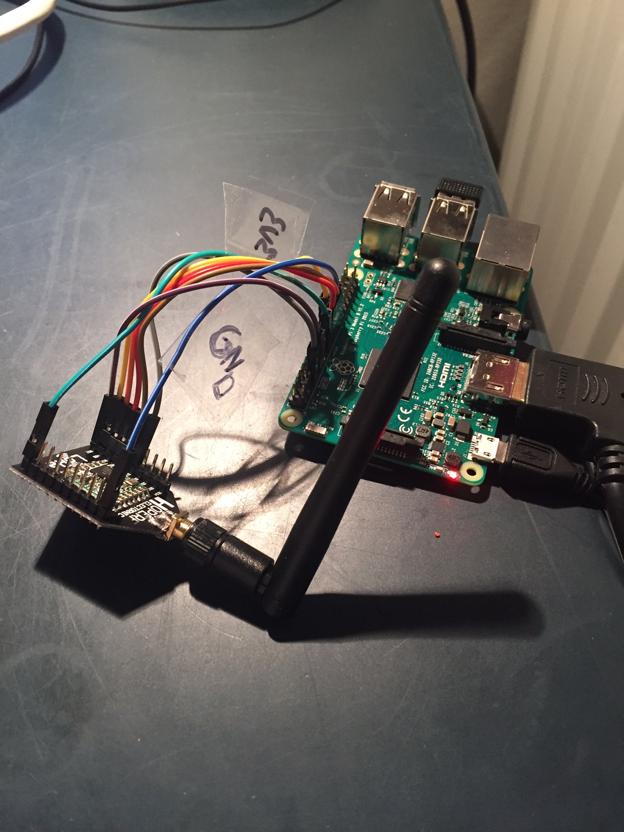
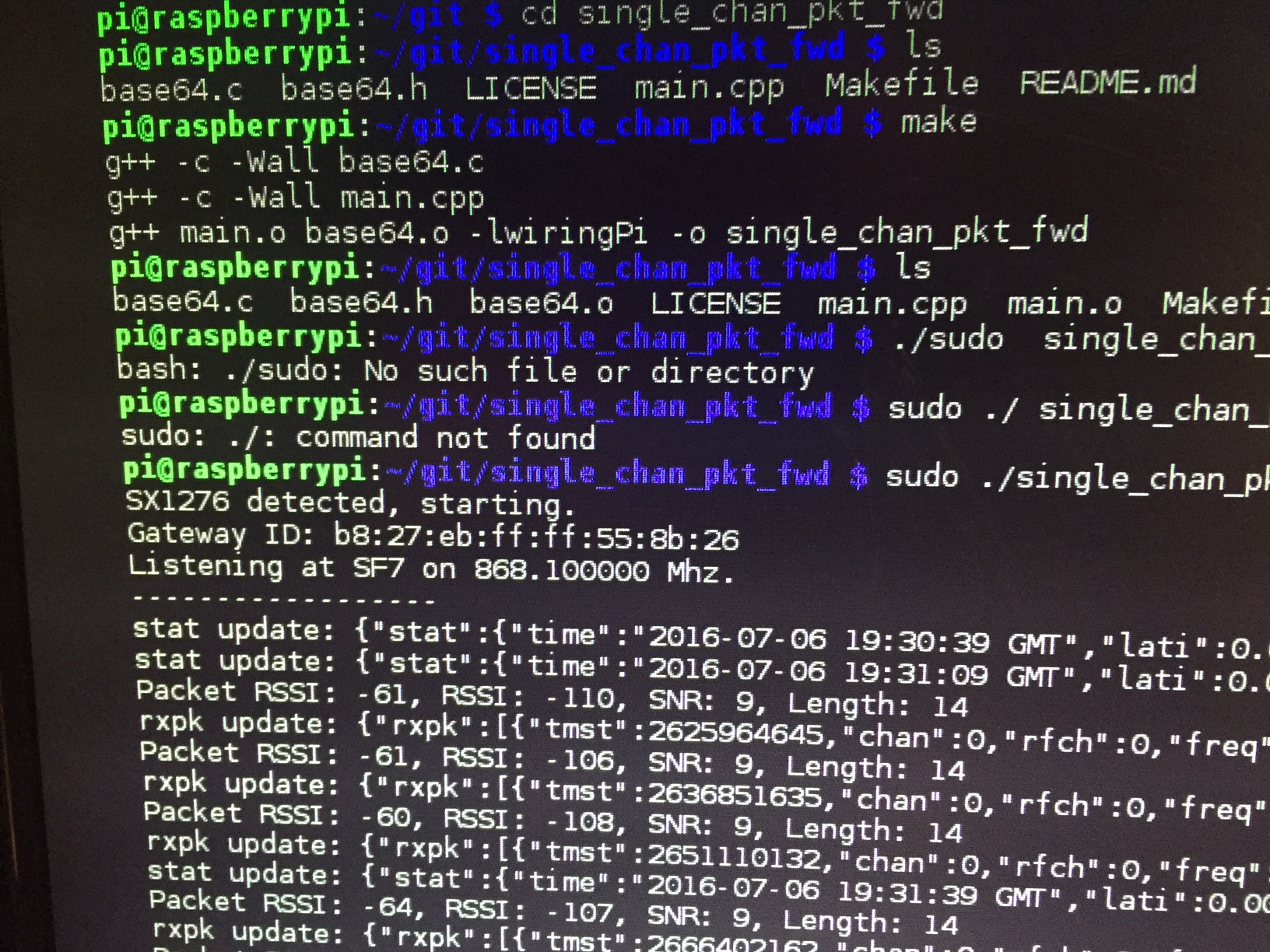
I have also built the following gateway, based on Raspberry Pi:
The gateway looks to be running fine.
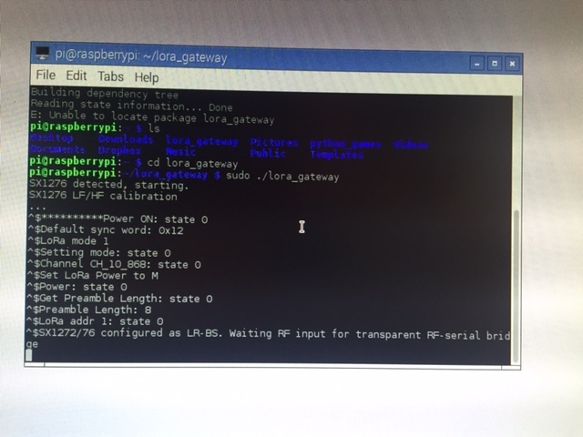
However, I am not receiving any packages on the gateway. Gateway and node are placed indoors, maybe 10 meters apart.
Is there some fundamental mismatch between the two devices / software that I am missing?
It looks like you are using a LoRa gateway, now a LoRaWAN gateway. LoRa is just the radio protocol used for LoRaWAN. Maybe you should look into using the components to build a single channel gateway (there is plenty of information on that subject available on this forum)
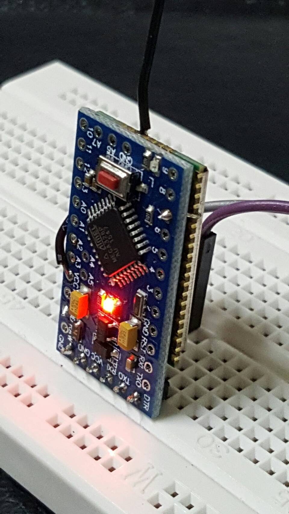
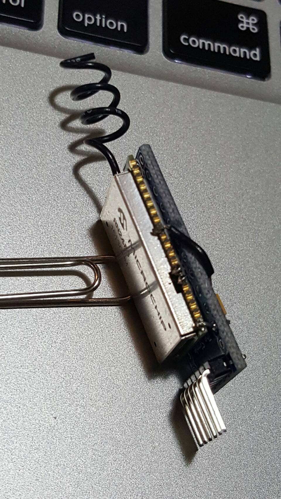
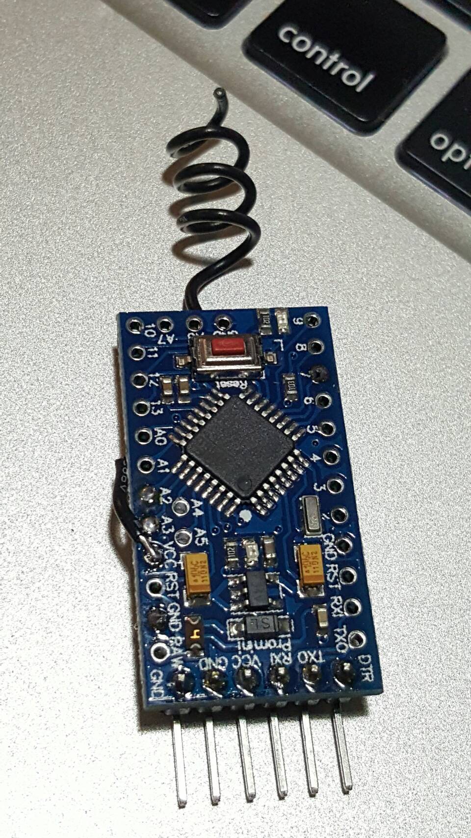
I made a small node with 5 wire-welding and modified pins mapping in the code.
3 Likes
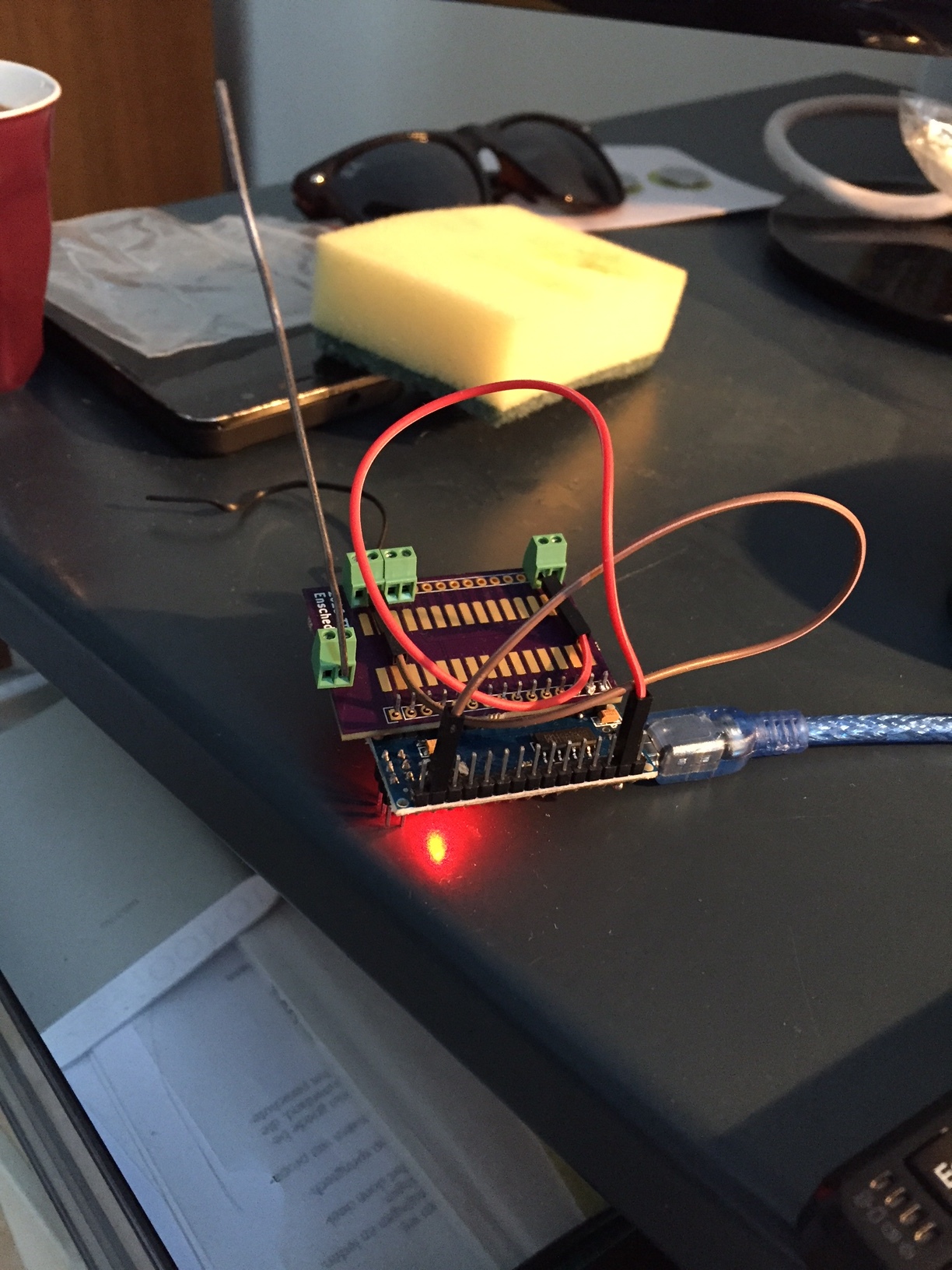
Got my node and gateway working as well!
Gateway based on RPI and SX1272
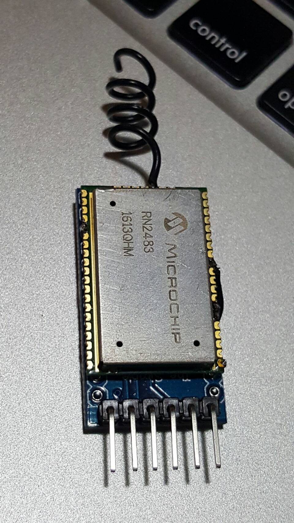
Node based on Arduino nano and RN2483:
2 Likes
Looks awesome!
Do you mind sharing how you made the connections between Arduino and the RN2483?
looks great. I’m very interested in more details 
Well, it’s sort of working. Gateway is receiving packets, but cannot see it in the TTN Dashboard, even after adding the following to my gateway main.cpp
https://www.thethingsnetwork.org/forum/t/new-backend-how-to-connect/1983/108
Anyone an idea?
As far as details go: I just followed the instructions from this topic and the instructions for the gateway in my link above.
Did not do any testing of range yet, but will do so this weekend.
Check out at: https://github.com/TumThings/ProMini-RN2483/
1 Like
Many thanks!
Thank you for the offer… I would like to have the PCB design.
And then … Where/How did you create the PCB… (Its looks very nice… )
thank you
Steven
I am in the process of putting together Arduino UNO and RN2483.
When compiling the TXfastViaTTN.ino get error from editing line 66 to read
myLora.initTTN(“B827EBFFFE9D3258”);
Error:
C:\Users\Dell\Documents\Arduino\TXfastViaTTN.ino\TXfastViaTTN.ino.ino: In function ‘void setup()’:
TXfastViaTTN.ino:66: error: ‘class rn2483’ has no member named ‘initTTN’
myLora.initTTN(“B827EBFFFE9D3258”);
exit status 1
‘class rn2483’ has no member named ‘initTTN’
what am I doing wrong:
Here is the setup section:
void setup() {
//output LED pin
pinMode(13, OUTPUT);
led_on();
// Open serial communications and wait for port to open:
Serial.begin(57600);
mySerial.begin(9600);
Serial.println(“Startup”);
//reset rn2483
pinMode(12, OUTPUT);
digitalWrite(12, LOW);
delay(500);
digitalWrite(12, HIGH);
//initialise the rn2483 module
myLora.autobaud();
myLora.initTTN(“B827EBFFFE9D3258”);
//print out the HWEUI so that we can register it via ttnctl
Serial.println("When using OTAA, register this DevEUI: ");
Serial.println(myLora.hweui());
Serial.println(“RN2483 version number:”);
Serial.println(myLora.sysver());
//ABP: init(String AppEUI, String NwkSKey, String AppSKey, String addr);
myLora.init(“70B3D57ED00001A6”, “AE17E567AECC8787F749A62F5541D522”, “8D7FFEF938589D95AAD928C2E2E7E48F”, “02017201”);
//OTAA: init(String AppEUI, String AppKey);
//myLora.init(“70B3D57ED00001A6”, “A23C96EE13804963F8C2BD6285448198”);
//transmit a startup message
myLora.txUncnf(“Fast TXer (TTN)”);
led_off();
delay(2000);
}
// the loop routine runs over and over again forever:
One other point …
I tried this on a 2nd backup laptop… and was able to reproduce my error…
My sense is there IS something wrong with this one line:
myLora.initTTN(“B827EBFFFE9D3258”);
What could it be? Thank you in advance
Steven
strange. for any reason I’ve removed that line in my code …
Hi skramer
That is a line of code for an older version of my library. Try downloading the new version of the library, and look at the new example sketch at https://github.com/jpmeijers/ttnmapperarduino.
The line “myLora.initTTN()” chaned to only “myLora.init()”, and depending on the parameters it is either OTAA or ABP. The example (https://github.com/jpmeijers/ttnmapperarduino/blob/master/TXfastViaTTN/TXfastViaTTN.ino) explains better.
Thank you… not quite there yet…
I have reviewed both .ino’s
I would like to bring to your attention on line 15 of both of them there is this line:
(maybe this is part of my confusion… )
"* The appropriate line is “myLora.initTTN(“XXXXXX”);”
Notice the “TTN”
and line 29
“* Remember that the serial port should be initialised before calling initTTN().”
So sorry I still don’t know where to put this line:
When I put “myLora.init(“B827EBFFFE9D3258”);”
B827EBFFFE9D3258 = Gateway EUI
Below you can find our sketch including changed line for ABP:
myLora.init(“70B3D57ED0000657”, “962AF160912588103D1E9981696126EF”, “C2FDF3EA389D272D2B9F0856BD8E3523”, “BDA12BD7”);
This is for an application on our Active gateway (Checked in ttnctl command line and in http://staging.thethingsnetwork.org/gatewaystatus/)
Maybe you can place the myLora.init correctly for us…
Thank you kindly
===============================================
This is the output from serial monitor
Startup
When using OTAA, register this DevEUI
RN2483 version number:
Here is the updated sketch with our string keys on line 75 and 78
#include <rn2483.h>
/*
- Author: JP Meijers
- Date: 2016-02-07
- Transmit a one byte packet via TTN. This happens as fast as possible, while still keeping to
- the 1% duty cycle rules enforced by the RN2483’s built in LoRaWAN stack. Even though this is
- allowed by the radio regulations of the 868MHz band, the fair use policy of TTN may prohibit this.
- CHECK THE RULES BEFORE USING THIS PROGRAM!
- CHANGE ADDRESS!
- Change the address this device should use to either a testing address or one from a range you “own”.
- The appropriate line is "myLora.initTTN(“XXXXXX”);
- Connect the RN2483 as follows:
- RN2483 – Arduino
- Uart TX – 10
- Uart RX – 11
- Reset – 12
- Vcc – 3.3V
- Gnd – Gnd
- If you use an Arduino with a free hardware serial port, you can replace
- the line “rn2483 myLora(mySerial);”
- with “rn2483 myLora(SerialX);”
- where the parameter is the serial port the RN2483 is connected to.
- Remember that the serial port should be initialised before calling initTTN().
- For best performance the serial port should be set to 57600 baud, which is impossible with a software serial port.
- If you use 57600 baud, you can remove the line “myLora.autobaud();”.
*/
#include <SoftwareSerial.h>
SoftwareSerial mySerial(10, 11); // RX, TX
String str;
unsigned long time = 0;
//create an instance of the rn2483 library,
//giving the software UART as stream to use,
//and using LoRa WAN
rn2483 myLora(mySerial);
// the setup routine runs once when you press reset:
void setup() {
//output LED pin
pinMode(13, OUTPUT);
led_on();
// Open serial communications and wait for port to open:
Serial.begin(57600);
mySerial.begin(9600);
Serial.println(“Startup”);
//reset rn2483
pinMode(12, OUTPUT);
digitalWrite(12, LOW);
delay(500);
digitalWrite(12, HIGH);
//initialise the rn2483 module
// myLora.autobaud();
// myLora.init(“B827EBFFFE9D3258”); putting this line here creates all kinds of new errors
//print out the HWEUI so that we can register it via ttnctl
Serial.println("When using OTAA, register this DevEUI: ");
Serial.println(myLora.hweui());
Serial.println(“RN2483 version number:”);
Serial.println(myLora.sysver());
//ABP: init(String AppEUI, String NwkSKey, String AppSKey, String addr);
myLora.init(“70B3D57ED0000657”, “962AF160912588103D1E9981696126EF”, “C2FDF3EA389D272D2B9F0856BD8E3523”, “BDA12BD7”);
Serial.println(“Debug3”);
//OTAA: init(String AppEUI, String AppKey);
//myLora.init(“70B3D57ED0000657”, “962AF160912588103D1E9981696126EF”);
//transmit a startup message
myLora.txUncnf(“Fast TXer (TTN)”);
Serial.println(“and how about here3”);
led_off();
delay(2000);
}
// the loop routine runs over and over again forever:
void loop() {
led_on();

Serial.println("TXing");
myLora.txUncnf("!"); //one byte, blocking function

led_off();
delay(200);
}
void led_on()
{
digitalWrite(13, 1);
}
void led_off()
{
digitalWrite(13, 0);
}
LoRaWAN transmits (broadcasts) data to all gateways within range. You do not specify a gateway ID on a node.
Awesome work guys!
What will be the tweaks needed to build an Arduino + RN2903 from this setup?
Hi Jairuz
Have a look at the command reference for the RN2903: http://ww1.microchip.com/downloads/en/DeviceDoc/40001811A.pdf
The main differences I spot are these:
For the RN2483 I use “mac reset 868” on line 98 and 178 of rn2483.cpp. These two lines need to be changed to “mac reset” for the RN2903.
In rn2483.cpp lines 129-131 and 181-182 can be omitted as they set the RX window for the 868MHz band, which is not applicable for the RN2903.
I hope you get it working.
Maybe in the future it can be useful for the library to auto-detect the module version and switch automatically. I however do not have an RN2903 to test.
1 Like