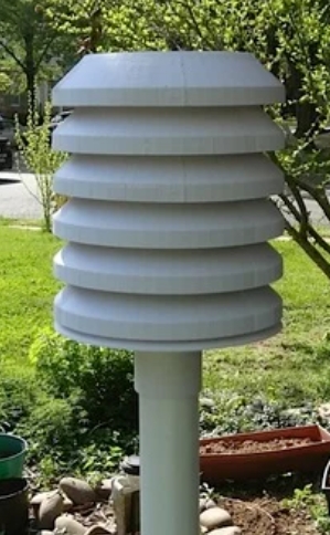
I would have made the hole closer to the sensor (aka on the bottom right)).
This was just the first enclosure I did and you’re quite right. When it was all put together I looked at it and asked myself “Why did you put that there?”, and I’ve never had a good answer…
How long do you’re battery last and what’s you’re send frequency?
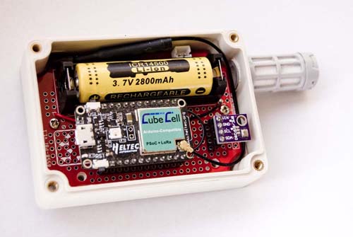
I’m testing a number of different batteries, but the ones in the photo, which are nothing like the rating they claim to be (i.e. more like 280mAh than 2800mAh), are lasting around 70,000 cycles with just the processor sending a message (two actually) every minute, so that’s getting up around 15 months if the interval is cut back to 10 minutes. With a 75mA solar panel—80x45, 5.5V—and a TP4056 battery management system hooked up (to a Heltec Wireless Stick Lite module), the node I have running at the moment has lasted three times as long as without the solar panel and is still going.
I’ve used several Li-Ion and LiFePO4 battery configurations and, with the exception of the cheap 14500 Li-Ion battery in the photo, their relative life is pretty much as rated, but I’ve not really tried very hard yet to optimise any specific configuration so battery life varies quite a bit depending on the processor/sensor configuraiton.
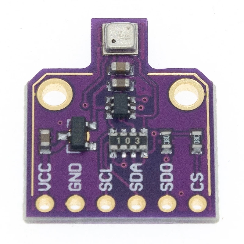
The CubeCell is only doing around 10,000 cycles on the '2800’mAh Li-Ion battery with the BME280 configured, but I don’t think I’m managing the power up/down of the sensor effectively, so there’s still a bit of work to do there. For battery comparison though, the same configuration runs over 20,000 cycles on a 700mAh (Soshine) LiFePO4 battery and this seems to be a more genuine battery rating.
In Australia, we use the 915MHz band and my [private] network is operating at 917MHz.
I haven’t done any calibration at all at this stage. I’ve been working on the basic hardware/software configuration and packaging of my application, but I’m relatively new to this game, so this is as much about learning at this stage as anything else.

 ):
):