I was just wondering if anyone ever programmed an ATmega 328P on a PCB directly (not using arduino)? Is it possible to use some kind of library, like the LMIC? I have a PCB composed of an ATmega 328P, a lora module, and some other components such as sensors. I would like to know how can I program it without using arduino. I want my PCB to retrieve sensor data and send it to my TTN application.
First off, an ATmega328P can struggle memory wise, as a LoRaWAN node, with some sensor setups.
To program the ATmega328P, you either need access full access to the ISP pins and use an ISP programmer, which can be difficult with a LoRa module in place, or the ATmega328P needs to have been programmed with a serial bootloader and you program it as an Arduino in the normal way.
Unless your well experienced in this area it would make more sense to start with a board that you know can be programmed.
…Can be programmed…and has enough memory capacity to allow a full, responsive LMIC/LoRaWAN stack and space for sensor(s) operation and local processing if needed, dependent on the application…
I have my full code working in arduino. I previously used it for the arduino pro mini which also uses an atmega 328P. Therefore, I know the memory won’t be an issue. However, I am wondering how can I translate that code to my PCB. I do have full access to the ISP pins and I have an ISP connector.
Hi Jeff, do you know how can I do it? I have a working arduino code that uses the LMIC Library. I want to translate that code in my ATmega 328P that is on my PCB.
Is it up to date code that supports the appropriate MAC commands of the more recent LoRaWAN specifications?
Google will reveal an embarrassing number of pages about using an ISP programmer with the Arduino IDE - if you look at the programmer options you’ll see that you can use an Arduino as an ISP programmer.
It’s always worth exploring the tools you have, you’ll be amazed at the facilities you can find!
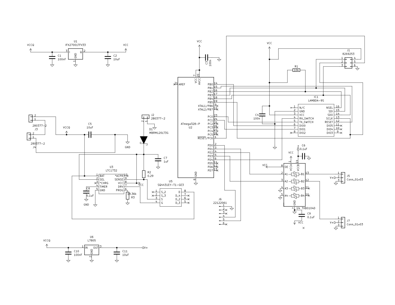
Using my quarantined machine, I checked out the attachment. Please repost as a JPEG or PNG - no point having people download things that don’t need to be. Thank you.
You might also want to expand on that you think we get a better idea of - as it’s a schematic and not a PCB, you say you have access to the ISP pins, all you need to do is look at the Arduino pages for how to use one as a programmer.
In the absence of any information on which library & which version and from experience on the forum with issues raised, I’d put my money on “not convinced” - depends on what the IO is for and if you are hoping for some near-real-time interaction to control things and/or how often that interaction occurs.
The LoRa module is one that needs seperate RX enable and TX enable pins. Thats not standard for UHF LoRa modules.
LMIC libraries do support the use of a single pin to switch between RX and TX, but that LoRa module needs two seperate pins to control RX and TX modes.
Maybe there is a version of LMIC out there that supports that particular LoRa module.