Got a response from iMST on my support call about forwarder not getting any new packets via SPI from the concentrator:
Yes, simple jumper wires may act as a kind of antenna. If some energy is being captured by this wires it can do a reset of the iC880A. So keeping the wires as short as possible and using a proper shielding is always a good idea.
There is a possibility to check if a reset occurred. But this is a kind of workaround:
*The HAL provides an API call named “lgw_get_trigcnt”. If the call returns a value of 2113929216 (0x7E000000) it is an indication of an unintended reset of the SX1301. *
Maybe you can add a check for this value in the main loop of the packet forwarder utility. If the software detects the value, a restart can be done in software…
I hope this helps as an intermediate solution.
Can you please keep us updated on this topic?
Thank you very much!
Will try better shielding and this workaround (one at a time) when I have access to my gateway again.
Have had no “hang” since I improved the shielding very prototypically (plastic and alufoil around the IC880A). Proves nothing yet. I still have long (15cm) jumper wires but the SPI is still running at 1 MHz instead of 8 MHz. (had slowed it up to be able to look at it with a cheepish USB-oscilloscoop)
The iMST ic880a might hang now and then. Seems to be related to some discharge reseting the gateway board while the Pi continue to work fine. Shielding and short connections seems to be the way to avoid the issue.
More weirdness here…
After moving the gateway to a different place in the office, resets increased (as measured by implementing a patch involving lgw_get_trigcnt). Weird thing is: when nobody is in the office, no resets occur. As most equipment is on 24/7, I’m beginning to suspect either the presence of people (not very likely), or the fluorescent lights that auto switch on/off depending on human presence.
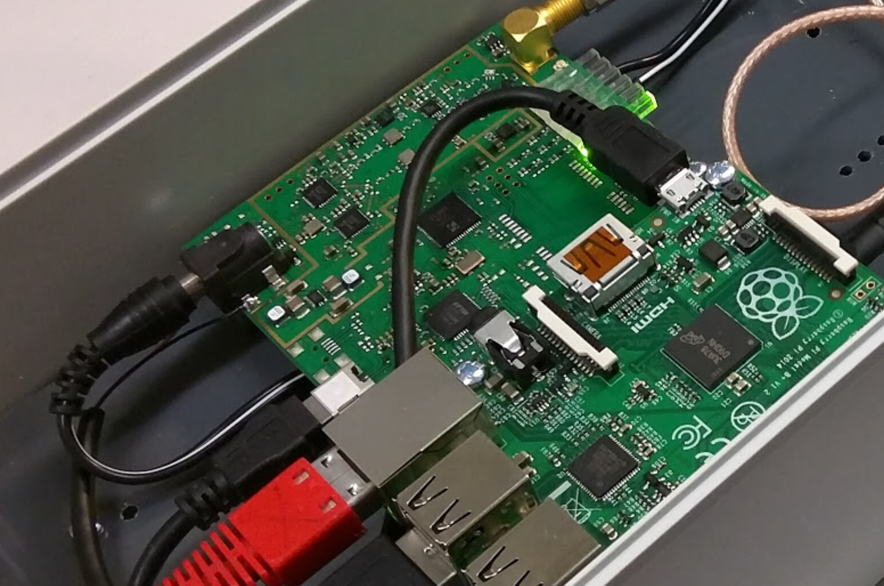
it all depends on how you built your system (photo?)
First of all, the aluminum case you referred to is not RF tight, there is no good electrical connection between the different (anodized) parts. It’s way better to take one of those ugly die-cast boxes
Use feed-through connectors for network and power and place some ferrite beads on the cables close to the box.
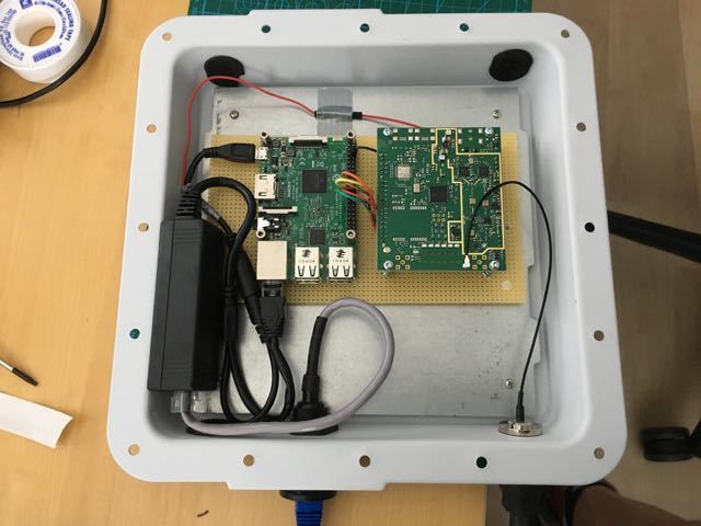
One note on the Raspberry Pi: there is absolutely no buffering or filtering from the IO signals from the processor in the RPi. The IO pins of the processor are not meant to be used this way, any wires running between RPi and IMST board need to be as short as possible. Let’s take the gateway from the picture posted by @JeroenB: you see wires running from the RPi GPIO connector on the right of the RPi board to the top of the IMST board. Twist that board 90° counterclockwise and make the wires as short as possible and if possible add some extra shielding. Place a ferrite bead around the power cable and plug the extra hole next to the RPi board. A cheap way to do this is to take some steel from a soda-can and solder it to the case. An easy way is to use special copper tape used for RF insulation.
I think it would be even better when a small PCB with buffers and filtering is placed.
@Rob65 thanks for your tips, I’ll rebuild the thing when I have the time. I’ll probably sandwich a “connector” PCB between the RPi and the iC880A, with as short as possible paths between pins. And use that butt-ugly case…
This is not my first Raspberry Pi project, and I’ve never used buffers, and it always worked fine. I’ve never seen projects using buffers on the internet either. The Lorank8 works fine as well, without buffers (AFAIK, the beagleboard might have builtin buffers).
I was rather hoping for an explanation for why it works with nobody in the office (with all fluorescent lights off).
I am under the impression the reset is likely to occur when “noise” come thru the power supply. I don’t have ic880a schematics but I suspect a lack of cleaning of the power rail.
I have the power supply plugged with a plug I unplug/plug regularly and often notice a reset after I play with the plug. The fact @melvin see stability when the power doen’t have spikes but see some issue when the light is switched on/off doesn’t seems far from my observations.
Maybe that says more about the power plug you are using … If it’s one of those standard plugs with a cental pin; there are about a zillions different types with different size of inner pin and outer diameter. Do not forget that the whole things takes between 300 - 600 mA depending of the load on the Raspberry Pi and if the IMST board is receiving or not. Filtering on the power lines or not, when there is a power interruption that lasts more than 10 ms, the board will reset - the capacitors on the board are just not big enough to bridge more time.
I have had this happening to me too: it all seems to fit but if the wind blows from the wrong direction the system resets.
Note also that the Raspberry Pi is a bit picky about its power supply. If the voltage drops below a certain point, the red LED goes of or starts flickering. If I run a Raspberry Pi 2B from the power supply + cable that came with my Samsung tablet I am bound to run into problems.
Developing a product is something else than just providing a schematic on the internet. The internet is not managed, anyone can write anything (as can I ;-)) but that does not make it the ultimate truth.
When we develop electronics products there are fully EMC testing by a certified testing laboratory and I’ve seen quite some issues with improper signal termination and wires between boards in a multi-board system.
Extra buffering, shorter cables, optimized cable routing or a PCB to connect the two boards are all things that will help.
The BeagleBone also has no buffers between the processor and the GPIO connectors. I remember from the manual that came with my BeagleBone that they warned about this. The LoRank8 uses an interconnect PCB between the BB and the LoRa concentrator board. This will most likely be a 2-layer PCB with one layer being a ground plane. That provides some shielding against EMC issues.
This may always stay a mystery… I’ve built quick & dirty demo systems with development boards with wires in between that run without any problems even when placed on my TIG welding table but I’ve also had systems that looked almost the same but had problems when the vacuum cleaner in the next room was switched on/off (note that with that vacuum cleaner in my own room I could not reproduce these problems).
Maybe it’s the refrigerator in the pantry which is triggering the problem.
Ok, I was wrong. Our gateways suffer from the same hanging problem. I was misled by the fact that our two best-positioned gateways (which are also the ones that are in my office’s reach), are the old USB version of the ic880a. But today @ursm did some testing and lots of our SPI gateways have the same issue.
I will try to implement a watchdog based on the workaround with lgw_get_trigcnt in the installer scripts, so that everyone can use it.
This is nice information: on the USB version there are no long wires running from board to the Raspberry Pi.
Try rearranging (resoldering) the wires from the Raspberry Pi to the IC880A so these are as short as possible. If the lines are longer, try to shield them or use twisted pair lines with each signal having a ground wire connected on both ends.
I now have two LinkLabs RPi gateway boards with the same sx1301/1257 chip set as on the IC880A running for a full week without any problems - with the antenna directly attached to the boards. This is basic the same design as the IC880A with the SPI signals running directly from the RPi to the sx1301.
This also directs the problems more towards the wiring between both boards.
@gonzalocasas How the ic1880a board are powered for the USB version? Are you using pin 21 and 22, or are you using the barrel plug?
I have a strong feeling one of the causes might be power fluctuations, as I regularly see my board reset when some appliance are turned on or of on the same power circuit. The power supply I use is a normal USB power supply for tablet (2.5A) and doesn’t cause Raspberry any issue, but maybe the power is filtered on the RPi while it is used straight on the ic880a, when using pin 21 and 22.
If I recall correctly (and see correctly), barrel plug powers the ic880a board, then from its pads to the usb power of the RPi. That worked well because the USB version had this remark on the manual about the order in which boards needs to be powered.
just to clarify: this is the USB version of the IC880A.
So if this works - with powering via the barrel plug - this seems not to be the problem.
One of the signals from the Raspberry Pi to the IC880A SPI board is the reset of the sx1301.
If somehow this signal picks up any glitches, this will reset the IC880A.
@gonzalocasas: do you also have a photo of the wiring of the SPI board?
I suggest that the best way of wiring these boards would be to mount the RPi below the IC880A with short wires from the IC880A to the RPi. Or rotate the RPi 180° such that the GPIO connector is close to the 21 pin connector on the IC880A
I see that you have a SMA connector mounted on the IC880A. Did you mount this one yourself? I remember seeing a question from another TTN forum user asking if he could just mount an SMA connector.
If you can, try adding a metal sleeve around the GPIO wires and ground this sleeve on both ends.
I sometimes use the metal sleeve of old computer cables: strip them and gently slide the new wires in the metal sleeve.
Or use some metal tape and solder a ground wire to both sides.
My gateway ‘hangs’ too once in a while. It looks like it is running, but packets are not received anymore.
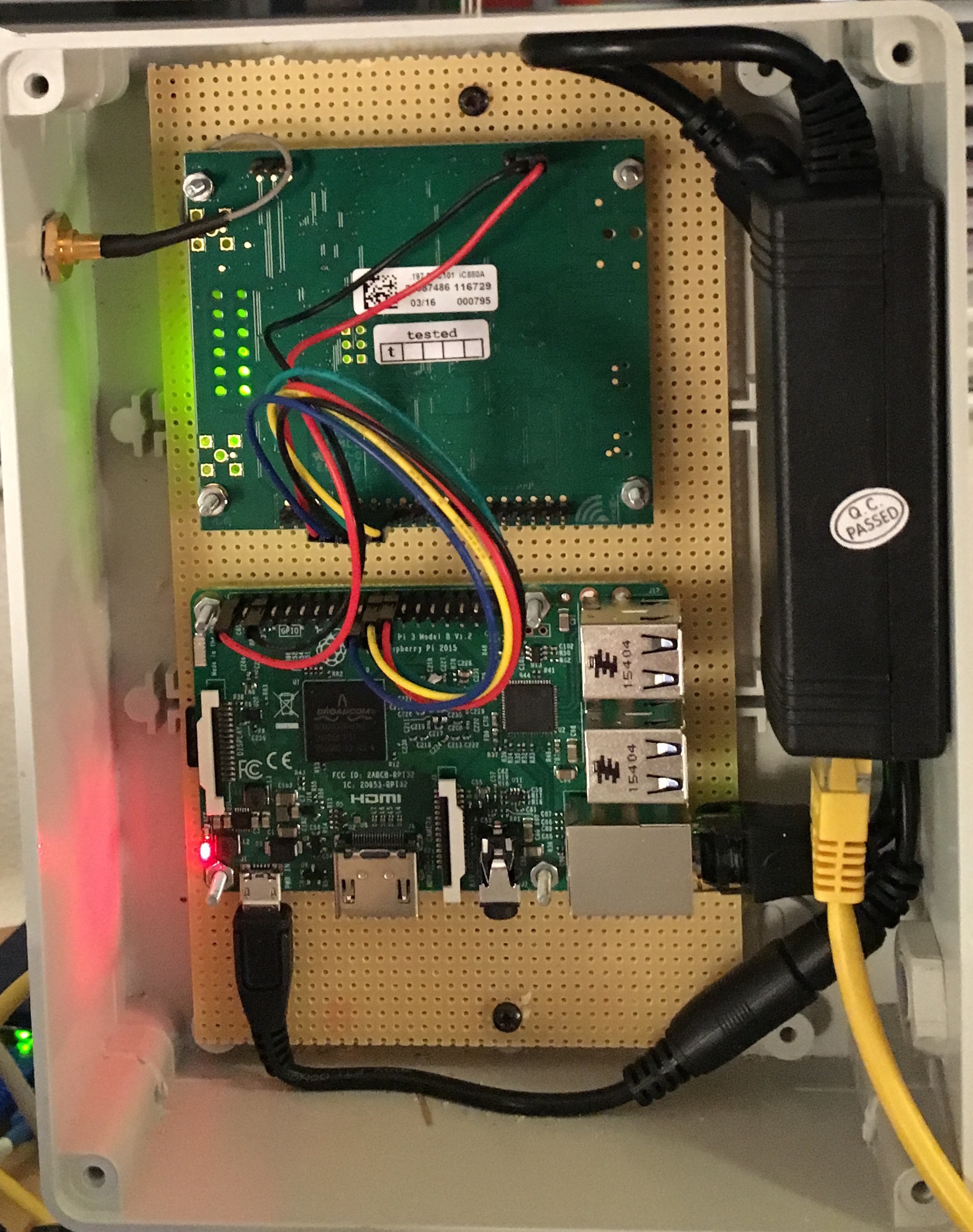
I used the instruction @gonzalocasas provided. In my case the pins of the concentrator are next to the rpi pins. The concentrator is powered by the rpi, and the rpi is powered through USB by power over ethernet IEEE 802.3af. Everything is in a plastic outdoor enclosure.
I think the power supply to the concetrator might be an issue, so I now have a ‘shield’ on the rpi that powers the rpi, and has seperate power pins for the concentrator, independend of the rpi. I used a scope to measure the difference 4.71v was delivered by the pi (before) and now 5.04v is delivered (stable) without sharing the current with the rpi (more available).
Next is to eliminate the plastic enclusure. And shorten the cables between the concentrator and rpi (maybe shield them)
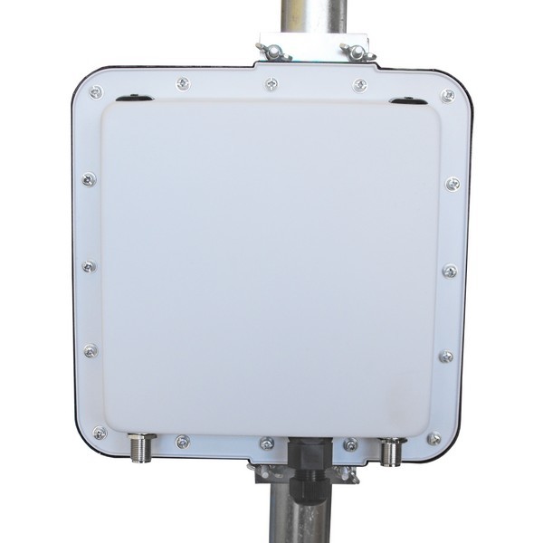
I’ve ordered this: https://www.aerial.net/shop/product/1102/ezynet-outdoor-enclosure-1-ethernet.html
(cheap!! shipping was more than the enclusure itself, so I ordered two and added some extra things I needed)
Once eveything is in the new enclosure I will report back my findings about this issue!
Cool stuff, @joris!
I’ll push an update of the installer in the next couple of days that monitors, detects a reset of the sx1301 and restarts the service accordingly, because regardless of shielding, if for whatever reason the radio board resets, the service needs to be able to recover.
We’re also working a backplane board to alleviate the EMI issues on the wiring part; once ready and tested, I’ll put it on OSH Park.
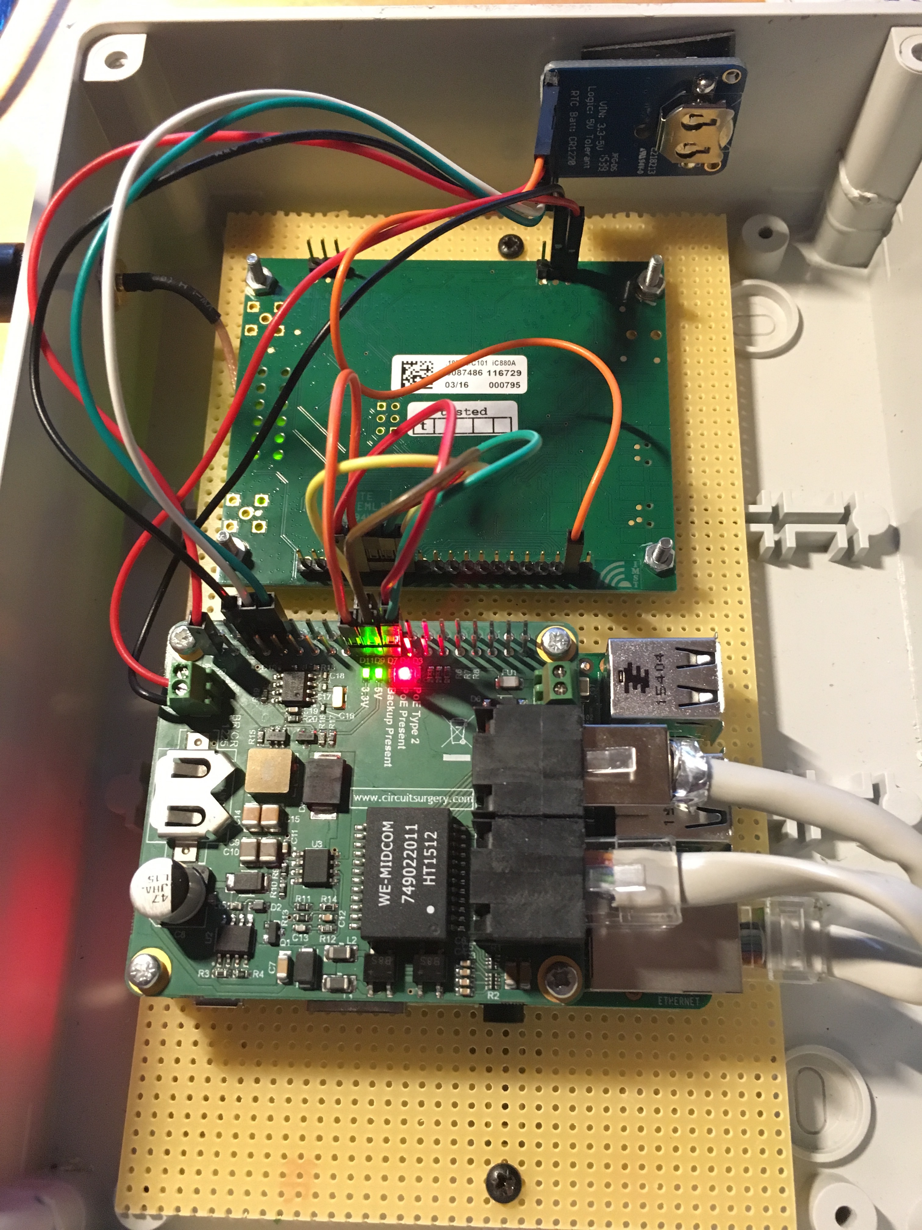
This is my new setup of the boards. I fried for some reason the POE Hat on the Pi, so I am now using a seperate POE adapter. I am supplying the 5v directly to the concetrator instead of the through the GPIO pin on the Pi.
I had a GPS connected in my previous setup, but due to the metal enclosure that is not working, unless I mount a gps antenne on the outside. However, the GPS does not provide anything usefull yet, so I lef it out.
The cables between the RPI and IC880A are short, but not shielded.
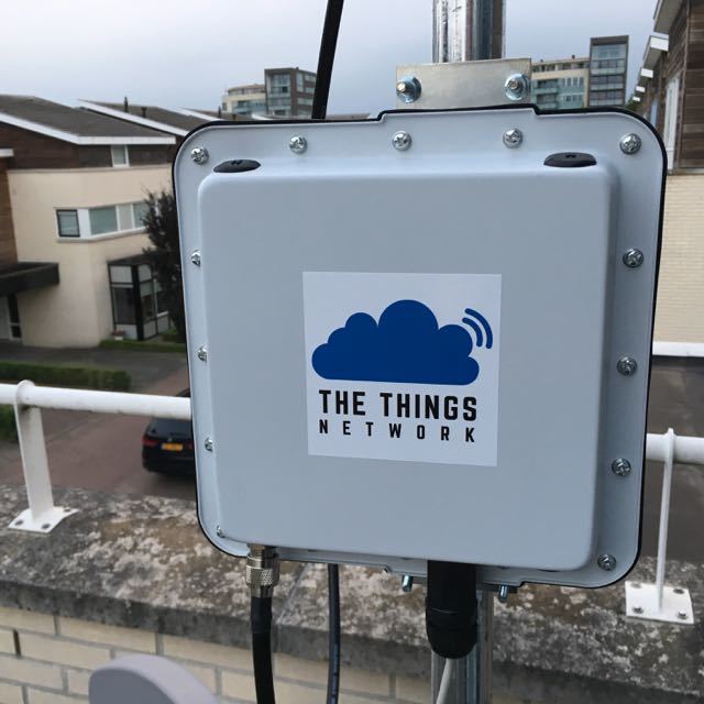
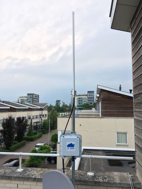
Hopefully the metal enclosure minimize the possibility of a “hang”. But regardless of that, I think the new enclosure definitely looks cool