I recently installed a Raspberry Pi / RAK831 setup using Resin.io. (with the RAK glass antenna)
The physical install was a bit more complicated than I would have liked, having to use a much longer antenna cable than ideal (about 10m to get the gateway away from birds, cockatoos in Australia can do some amazing damage).
Real world range is a bit disappointing at about 6-7 km at the moment.
Can I / should I boost the gain on the RAK831 to improve coverage and counteract the losses of the longer cable?
The gateway sits on a farm where it is roughly 20 km to the boundary, so unlikely to upset anything else in the ISM band.
@Paul as you will be loosing power in both transmit and receive there is no point increasing the transmit power of the gateway as it still won’t hear the node. You should look at lower loss antenna cable and/or higher gain antenna. If the nodes are generally in one direction you can get antenna gain by using a directional antenna on the gateway. If you know the cable type and the actual cable losses we can calculate the actual antenna gain you will need. if you want, you can publish the antenna cable type here, I can show you how to calculate. If you don’t know the type, measure the diameter and we can estimate losses. Another option is to put a directional (higher gain antenna) on each of the more remote nodes. In all of these options we need to be sure you don’t exceed the maximum EIRP which in Australia is +30dBm on AU915 (far higher than elsewhere around the world) Now the biggest benefit you will get is antenna height. What heights have you installed the gateway and nodes. You can also plot the radio signal Path by using Google Earth (the downloaded version) where you can see a cross section of the terrain.
I have about 10m of RG58 so looking at about 5db loss, antenna is a 5db gain by RAK. It had to be thin enough to fit inside the mast.
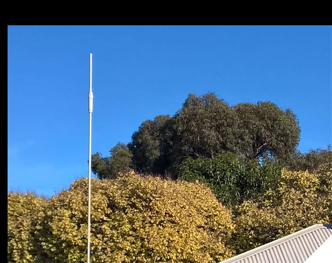
Antenna at the moment is sitting about 13-14m above the ground, which is above the canopy of surrounding trees/vegetation, terrain is flaaaaattttt.
Cockatoos and heat were our main issues with wanting to get the gateway under the roof, at the moment the cable runs inside the mast pole so completely protected apart from the last 20cm or so which is covered in flexible metal sheath conduit.
When we put the antenna up, we had a look at the TV antenna that was also up there and the cockatoos had bent every single radial fin on the aluminium antenna, they are savage.
Could try some higher gain antennas at the nodes.
So I was looking for an easy answer to try to get more range, maybe there isn’t one.
See if you can get the node antennas 3m above the ground, that will make a big difference in reducing the path loss on flat ground. probably simpler than obtaining gain antennas on the nodes. Remember, this only applies to the nodes greater than 7Km from the gateway. if you apply the same to the closer nodes, you may reduce current draw and if battery powered, increase battery life.
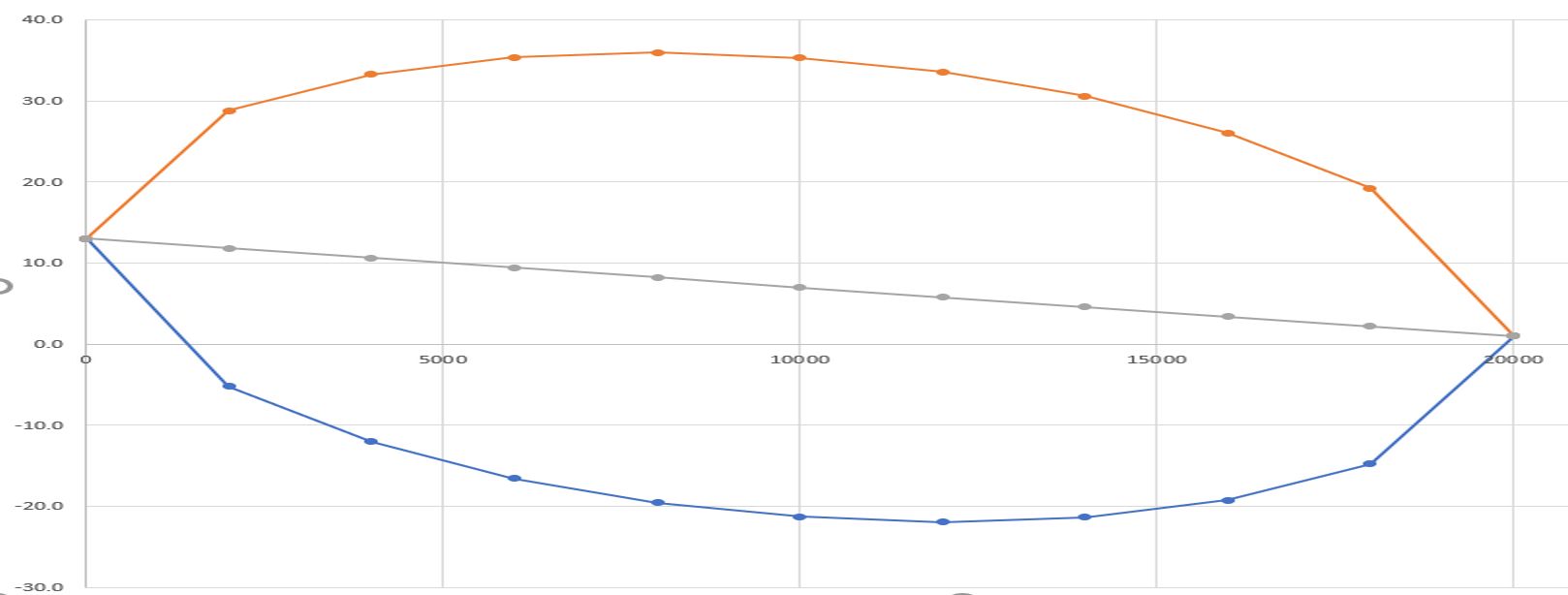
@Paul here is the plot of the Freznel Zone, you can see a significant proportion of the path is below the ground (below the zero line) and so this signal doesn’t make it, it’s adsorbed in the ground. I am about to install something similar and just sorting out Gateway locations, so really interested in your findings.
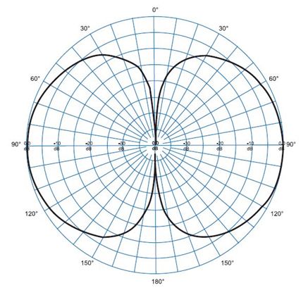
@Paul_Stewart, you could look at a higher gain antenna on the Gateway. You would need an antenna with another 5dB to overcome the cable loss. ie go up from a 5dBi antenna to 10dbi. Now there is a trap with higher gain antennas, the gain vs direction profile is not as smooth as a lower gain antenna. As an example, a Dipole has a gain of 2.2dBi but the shape is smooth.
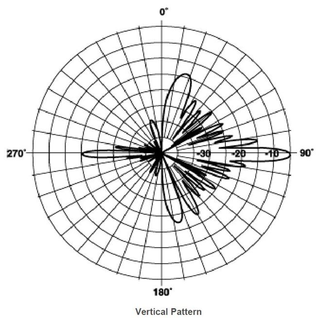
Now compare this to a higher gain antenna, in this case a 16dBi colinear antenna
In this case there are severe notches in the antenna’s profile. If you happen to have a Node in the direction of one of the notches, it won’t connect, while a node further away will. That will cause all sorts of confusion.
In your application of flaaaaat ground, all the nodes will be within a few degrees of the horizontal and be in the main lobe. Put this same antenna on a hill top and some nodes will have very poor signal.
So if you try a higher gain antenna, check out its gain profile before you go to all the effort of installing.
Hi Paul,
Please be so kind and tell me the location of the gateway antenna plus height of the antenna, antenna type and the same for the node. Based on that I will make you a simulation free of charge.
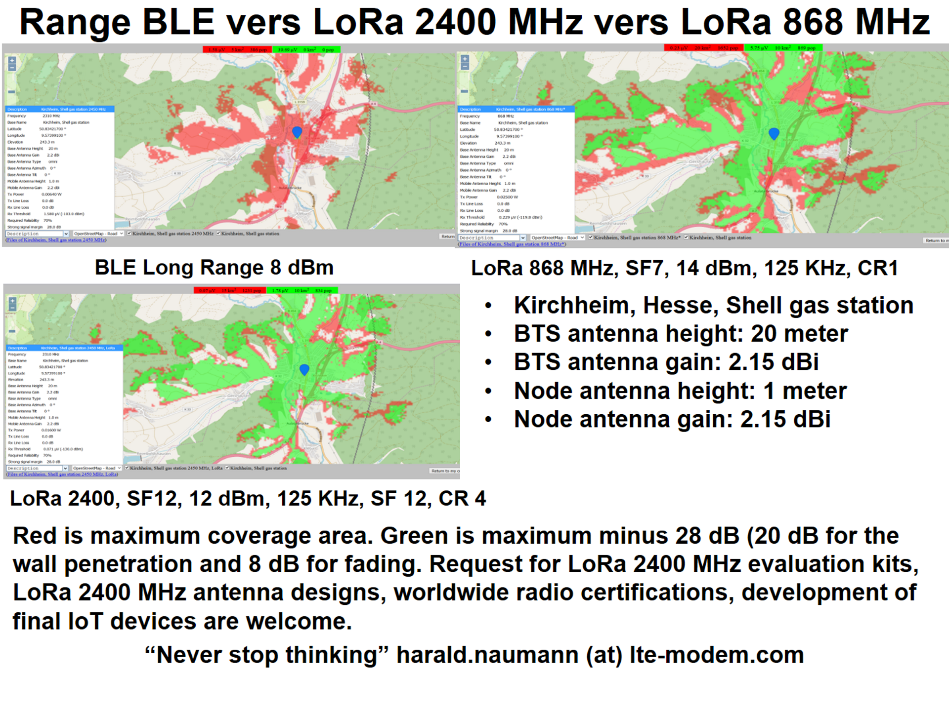
Simulation for Kirchheim, Hesse , Germany, the village were I was born:
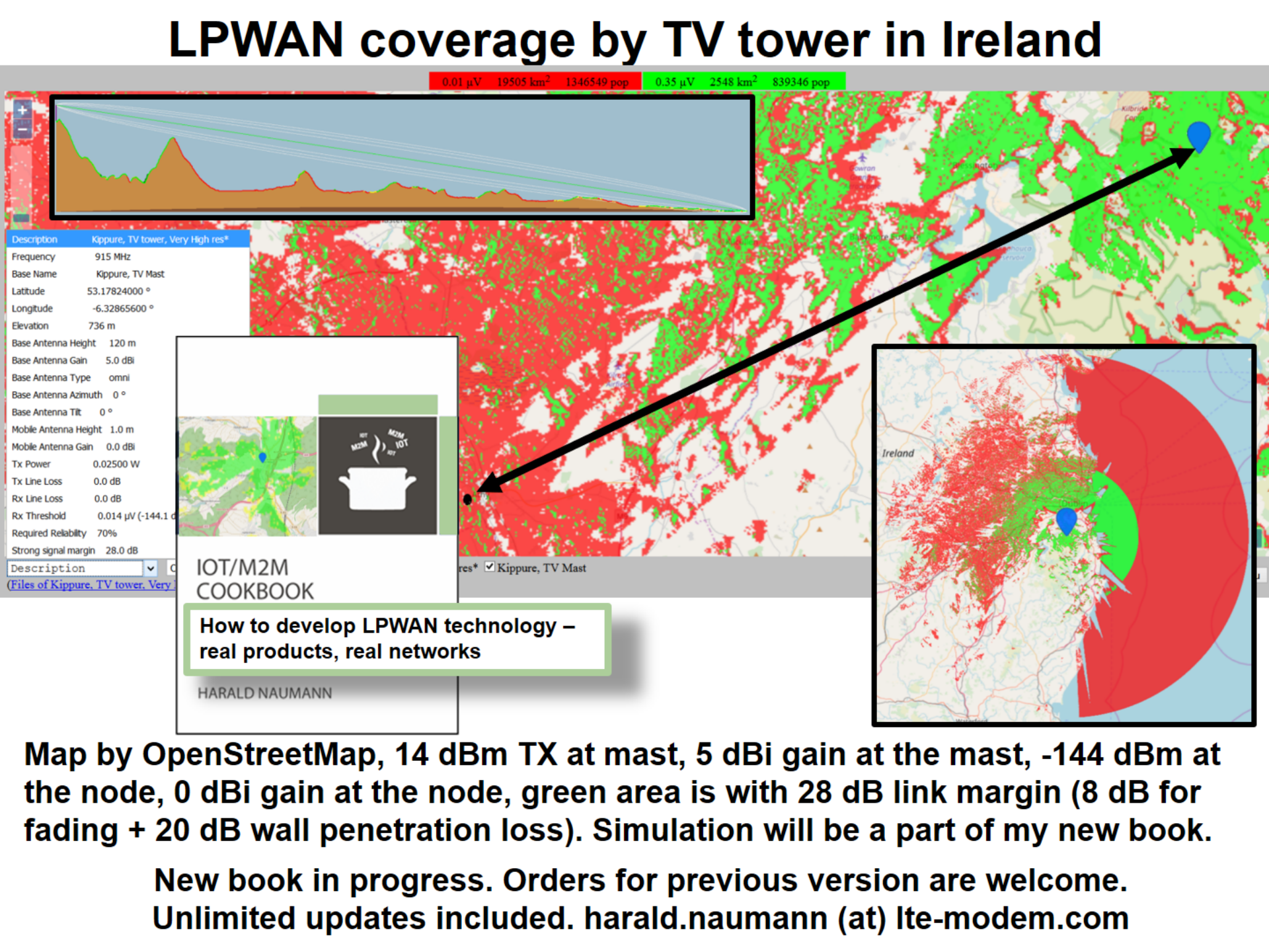
Simulation for a TV tover in Ireland:
Planing of private LPWAN wiil be chapter i my new IoT / M2M Cookbook.
I was out at the farm yesterday and we discussed the gateway hardware and will do something different in the future with cable and gateway location.
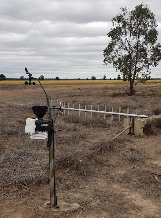
In the mean time we put a weather station in and initially used a small whip antenna (2dbi I think) which have performed well in the past on a Sodaq Explorer board.
SNR was between -1 and -5 db, so uplink messages were still getting through but downlinks may have been a problem.
Farmer suggested we try an old 850/900 Yagi mobile phone antenna he had spare, which we think is about an 8dbi gain.
SNR went up to 8.5-10, so although that antenna may not be tuned to 915 perfectly, it is obviously still doing the job.
This will be a temporary solution until we fix the gateway end.
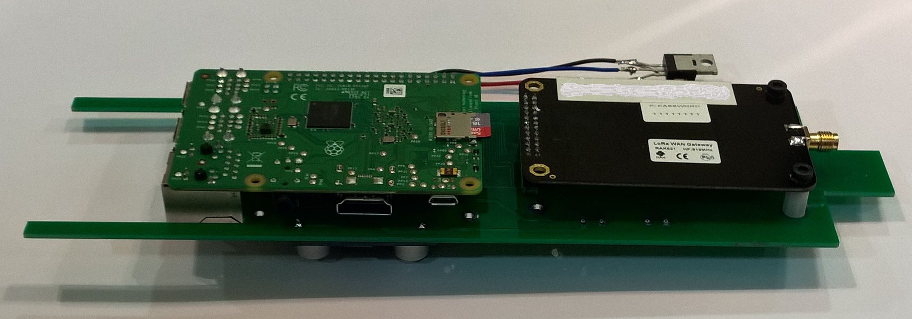
Hi Tony, I really like your RAK831 mounting on top of the mast and would like to do something similar. Do you have any other photos and/or info on the housing and antenna mounting integration?
@Sandgroper, Actually I don’t have many photos. I built my own pcb to rearrange the Pi and RAK831 into a thinner arrangement which fits into a tube. The only problem there is a lot of machining to turn a piece of plastic to fit the bottom of the tube and the top of the pole. Antenna rests on top of the PCB and connected via a short coax cable using N-type and SMA connectors. My challenge is temperature rise with the heat generated by the Lora chips and to a lesser extent the Pi when added to the heat load from the sun.
I am working on a new design which solves all these problems, I hope to start building in a month or two.
One technique you might consider is to use a double walled enclosure. The inner layer would look very much like you existing enclosure. The outer layer would be open on the bottom and vented at the top using a hood. The outer layer would be exposed to direct sunlight and therefore suffer the effects of heating via solar radiation.
The air gap between the outer layer and inner layer limits the temperature exchange between the two layers enabling you to concentrate on managing the heat dissipation for the inner layer housing and associated electronics. You could add a small fan to draw air from below which passes between these two layers with the fan effectively venting to the outside air.
Hi @Sandgroper, yes I know that technique as a “tropical cover” and my first gateway had that as a concentric second tube acting as a shade cover. Even with this the issue is still about is dissipating the heat from the Lora chips. Today is 41C ambient temp and the gateway is in full sun. My feeling is gateways are designed with cool climate countries in mind. However I think (believe) I have a solution, just need to get some time to finish the development
Perhaps you might look at using the Pi Zero to reduce power consumption. I tested the current consumption of my RAK831, Pi Zero and OLED setup and it draws about 210mA up to 310mA peaks from the 5volt supply. Assuming an average current of 300mA (it is definitely not that high) this gives a power consumption of 1.5 watts. Assuming also that we power the setup from a higher voltage and use a switching mode power supply to derive the 5volts, then allowing for the loss of efficiency, the power consumption should be about 2 watts. Even with an ambient temperature above 41 deg C, it should be easy to accommodate the cooling requirement using the “topical cover” approach.
 Cable losses for some of the more common cables. (This is a slide from my Lora Antenna presentation)