consider :
1 Like
Thnx so much . exactly what I was looking for
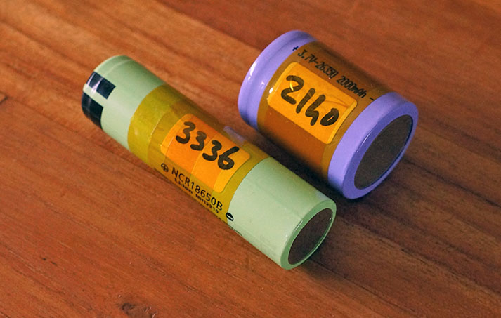
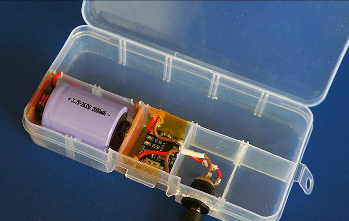
diy 26350 charger 
1 Like
As always: be extremely careful with Li-Ion batteries bought from dubious sources. Not six months ago I bought some 18650 branded Ultrafire that were giving me a voltage of 3.8V… when fully charged. I’ve never figured out what they were, exactly, but they sure weren’t Li-Ion cells!
Otherwise, why not using LiPo flat cells? your PCB looks one-sided, so you could stack them on the back. Just don’t stick a knife through those…
1 Like
Seems it is hard to find a SMD battery holder for this model :)))
I will have to design mine, I’m afraid
you bought the worst battery’s ever made … ultrafire ![]()
1 Like
yes true, been there
I’ve looked at this solution
those 26350 are excellent quality, but for a production I would contact the factory, can you still buy them next year ?
[ this is my favo lipo dealer ]
thats a much cheaper keyboard solution 
1 Like
well, to be honest, much more expensive.
but dealing with the BlackBerry Q10 keyboard connectors is a nightmare
ah ok, I thought that blackberry keyboard was very expensive.
complicated project… how’s the firmware going ?
1 Like
q10 bb kb are only 4 USD but the hirose 28 pin nano connector is awfull.
firmware is the one of ESP32 dev board.
I have mst of thel the functions in C done.
just need to assemble the puzzle’s pièces.
1 Like
looking good !
Hi, is there any update on this project? There is an agricultural use case for this here in Ireland. Thanks. Albert.
1 Like
What’s the status today? Remembering 5 months later?
Finally you did it with touch screen which is great! Buttons sucks )
1 Like
Yes. I will work on the Q10 keyboard part but later. I need to add another microcontroler for the keyboard only.
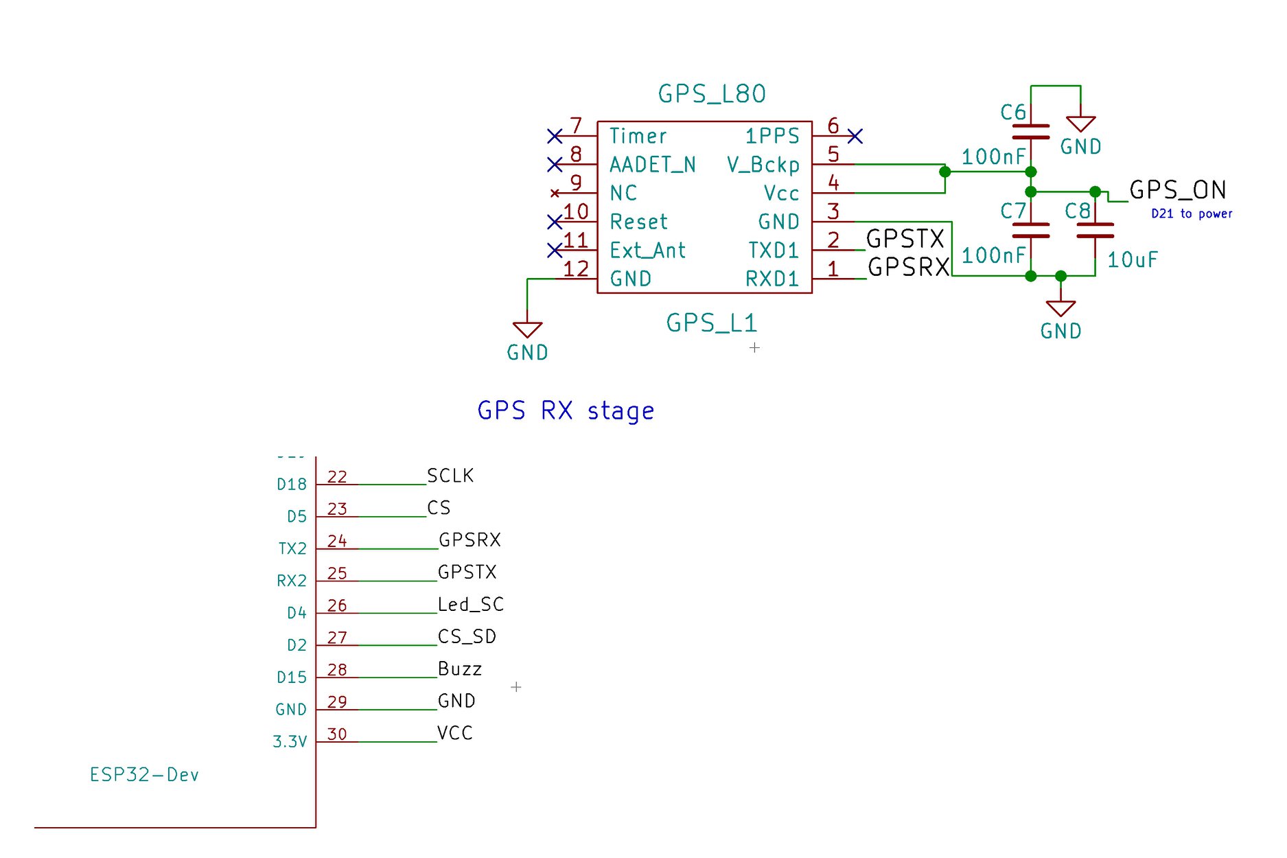
Now fighting with the GPS from QUECTEL L80-R connected to TX2 RX2 of a DOIT ESP32 DEV BOARD. And TinyGPS++ arduino library. My first time with GPS. I’m a bit lost. Impossible to get information from the GPS module YET. All the other functions are working well. Now making the software, designing the graphic menus …
What do you mean by ‘impossible to get information’? Usually GPS module sends lots of data when it is connected. If not then may be you have problem with satellite signal or interface?
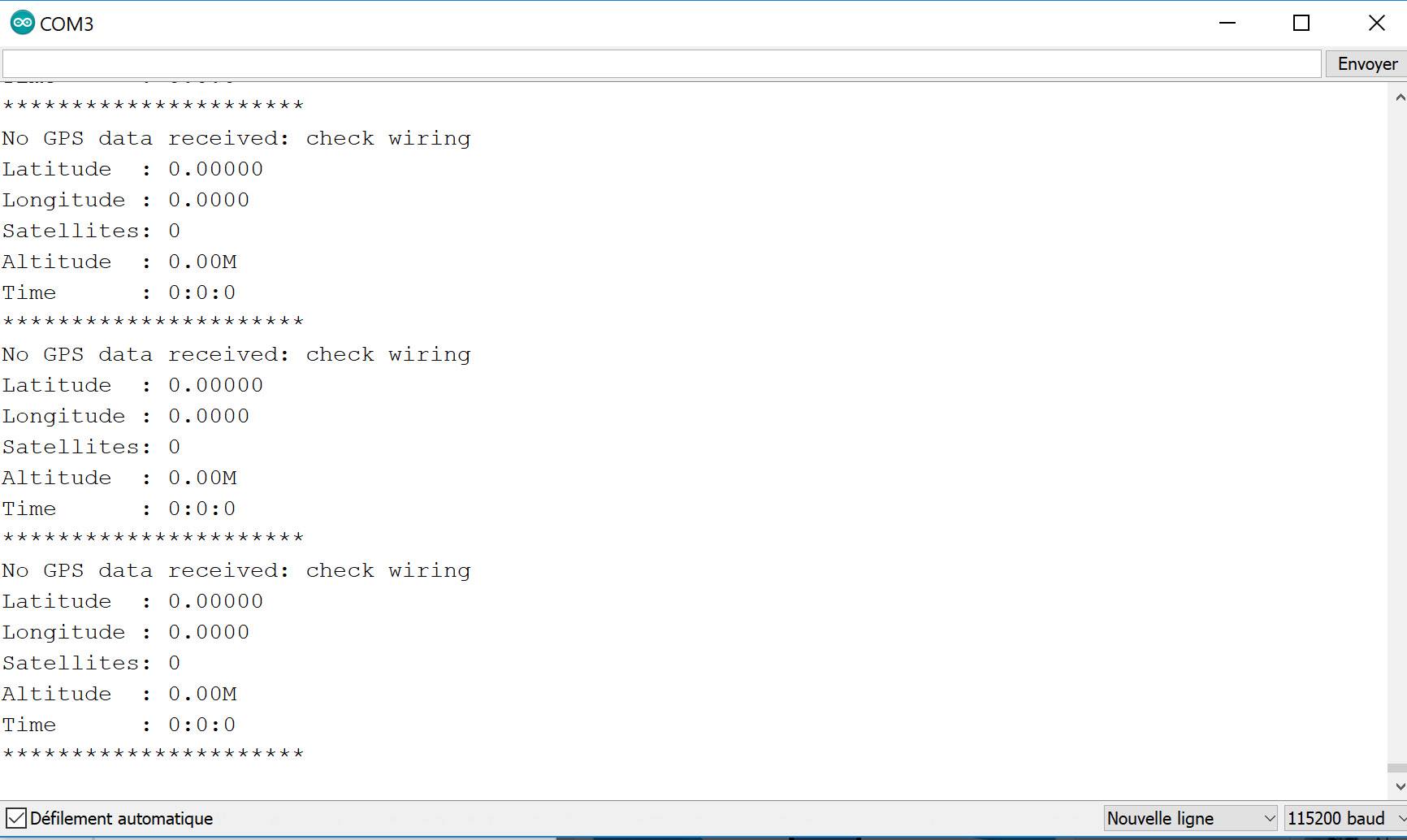
This is the first time I deal with GPS module. I’m becoming mad with such a simple thing … I cannot get any informations out. I’m probably doing something silly because I’m not used to .
After 5 minutes under the satellite. Nothing on UART2 RX from the GPS module
#include <TinyGPS++.h>
TinyGPSPlus gps;
HardwareSerial Serial1(1);
void setup()
{
// Setup GPS ON PIN 21
pinMode(21, OUTPUT); // sets the digital pin 13 as output
digitalWrite(21, HIGH);
delay(1000);
Serial.begin(115200);
Serial1.begin(9600, SERIAL_8N1, 17, 16);
}
void loop()
{
Serial.print("Latitude : ");
Serial.println(gps.location.lat(), 5);
Serial.print("Longitude : ");
Serial.println(gps.location.lng(), 4);
Serial.print(“Satellites: “);
Serial.println(gps.satellites.value());
Serial.print(“Altitude : “);
Serial.print(gps.altitude.feet() / 3.2808);
Serial.println(“M”);
Serial.print(“Time : “);
Serial.print(gps.time.hour());
Serial.print(”:”);
Serial.print(gps.time.minute());
Serial.print(”:”);
Serial.println(gps.time.second());
Serial.println(”**********************”);
smartDelay(1000);
if (millis() > 5000 && gps.charsProcessed() < 10)
Serial.println(F(“No GPS data received: check wiring”));
}
static void smartDelay(unsigned long ms)
{
unsigned long start = millis();
do
{
while (Serial1.available())
gps.encode(Serial1.read());
} while (millis() - start < ms);
}
I also had much trouble.
One issue was I wired the GPS to normal serial when it only worked reliably using 3.3v TTL… I was getting bad sentences, so my lora decode was presenting gibberish. I bashed away for days before I gave up and tried to just display the raw feed from the GPS, and realized it was bad. I used a TTL 3.3v usb adaptor to connect directly to the GPS, and saw that it was good, it was just how I had it connected - .
I was using a Wemos D1 Mini (ESP 8266) like you.
My suggestion is bypass the Arduino, until you get data from the GPS directly to Putty on PC using USB TTL. If your GPS won’t send data to a PC, it’s not going to work with the Arduino…
Try something like this. https://core-electronics.com.au/usb-to-ttl-serial-uart-rs232-adaptor-pl2303hx.html
I’ve spent ages on GPS nmea feeds at 4200 (standard speed), I might be able to help more.
1 Like