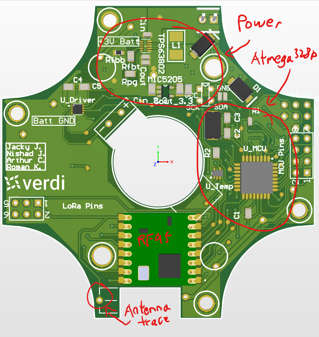
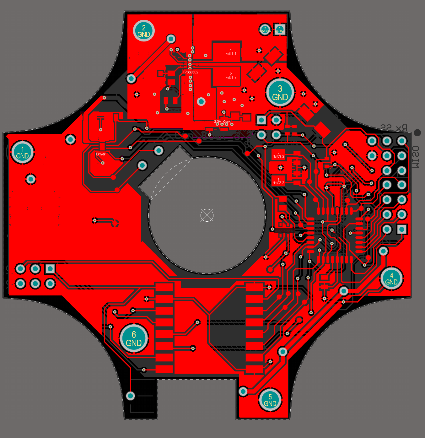
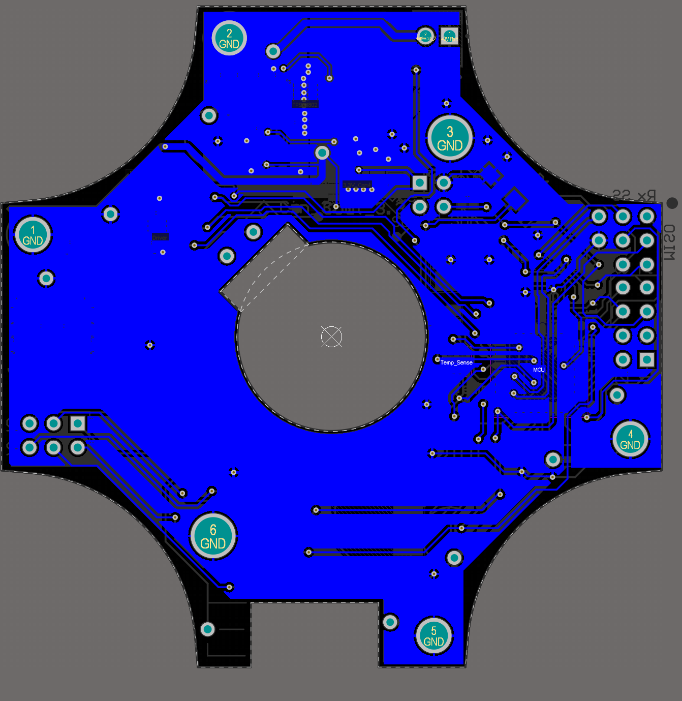
I made a PCB with a RF95 and a Atmega328p. It is extremely disappointing in terms of range and reliability. Here is the top and bottom layers of that PCB.
This is the PCB
This is the Top Layer
This is the Bottom Layer
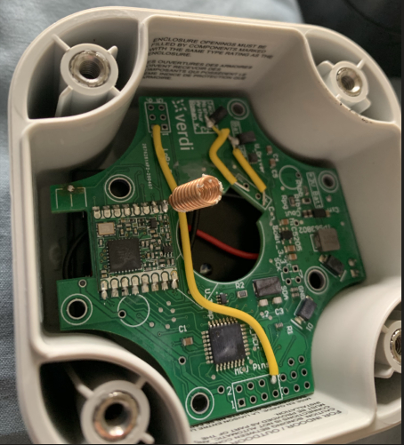
I know I made a mistake in the trace of the antenna, but even after I modded it so that the antenna is directly solder on the ANT pin as shown in the picture below, I am getting a 50% uplink rate at only 125 meters (in an urban area, more or less line of sight).
Is there anything obvious I am missing? It’s been giving me a lot of headaches.
Thanks !
I’d also look at what the firmware is doing - if it’s nearer the gateway, does that improve the uplink rate - if not, maybe the 328 is overloaded - the LMIC library makes for a very tight fit these days and I’ve sat and watched my small devices crash, hang and generally misbehave entirely down to software - and given the permutations of sensor checks / values etc, it can appear quite random.
Yes noted.
That antenna trace placing was pretty dumb.
I get the same with a quarter wavelength wire as I do with the helical antenna. Around -60 RSSI at 2 meters away from the gateway. Placing the antenna does help (brings RSSI up from -80).
Your firmware has actually been working quite well for me . But I’ll keep a close eye on the firmware. I am definitely switching MCUs for the next iteration.
What sensors do you have on this device - it’s so very easy to add just one more function that chips away at the free memory on each loop and then it locks up.
I’m looking at the ATmega4808 for simple devices - like a Arduino Nano Every but with less pins - if I need lots and lots of IO I’m veering towards ATSAM as Microchip seem to like making it easy for people to use their products.
My application is super simple. It actuates an valve that’s it.
It has a temperature sensor just for giggles and it monitors its own batteries but that’s nothing more than just keeping track of some states and using the Atmega328p’s analog pins.
I am looking at using ATSAMD21 for the next iteration cause it’s used on the Feather M0. Also looking into one of the RAK API-based modules or GlobalSat’s LM-130H1
Yes, but have you chiseled the erroneous trace right at the RFM95 pad, as previously commented? Your photo makes it seems that you haven’t.
That’s not absurd though I think it could be stronger.
Perhaps try moving the node progressively away from the gateway while watching the RSSI. Pay particular attention to any differences between the packets that do get through and those that do not.
What is your gateway? Are your sure your gateway’s antenna is actually connected to its concentrator deck?
Type quietly, don’t want @cslorabox to hear us, he’s not keen on these modules.
I’ve a cleaned up RUI template that I’m about to attach a simple sensor to. Once I’ve verified an I2C sensor I’ll put it on GitHub.
Can’t find anyone selling GlobalSat’s stuff in Europe and the feedback on here doesn’t look great.
I’m looking at the 4808 as it has enough IO, if it’s not carrying the burden of running LMIC it has acres of flash 48k and enough memory 6k and it can be made Arduino compatible for co-development with clients.
And for SAMD, I’m porting some previous work to the RAK4260 which is a ATSAMR34J18B. RAK have done all the RF work (which isn’t my thing) and it’s fundamentally the same (with a couple of pin allocation changes) to the SAM R34 Xplained board so plenty of support materials to hand.
But looking at the plethora of castellated modules around, I’m wondering if I can get away with putting a sticker on the top of the RAK modules and starting up my own pan-global IoT silicon manufacturer.
A couple years ago I would have agreed with you about ATSAMD family. However, having worked with the SAMD for quite a while now there are some issues. A couple of them are related to silicon bugs that have not been fixed and the lack of a UART/I2C/SPI FIFO. Another, larger issue, is how the peripherals interface with the internal bus. The way Atmel implemented the peripheral bus interface results in either a bus stall or a blocking wait to “SYNC” the peripheral registers. This is particularly troublesome when using an RTOS and the RTC is used for the kernel timer and can result in 100’s of us to several ms of delay when coming out of sleep. I think this issue is why it is difficult to find an RTOS that works tickless with SAMD.
If I was starting over again, I would take a close look at the nRF52840. Better power consumption, more peripherals, 4x the memory and it doesn’t appear to have this weird sync issue. You also get Bluetooth and an 802.15.4 radio.
 . But I’ll keep a close eye on the firmware. I am definitely switching MCUs for the next iteration.