@Halfbrain Working on getting your program working and so as you suggested I will follow your instructions EXACTLY.
To that end I have:
mDot
Conduit Setup to poly packet forward to TTN
MAX44009
MPU9250
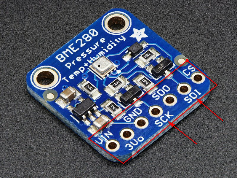
BME280
So I would like to start by getting ONE of these working.
I will choose MBM280 to start
That would be APPLICATION_MODE_3
I have your program setup as follows:
main.cpp
++++++++++++++++++++++++++++++
#include “Application.h”
#include “ApplicationConfig.h”
#include “UARTTunnel.h”
int main() {
Application application;
application.init(APPLICATION_MODE_3);

while (true) {
	//sleep();
}

return 0;
}
+++++++++++++++++++++++++++++++++++++++
and
ApplicationConfig.cpp has LORA_MODE_1
+++++++++++++++++++++++++++++++++++++
case APPLICATION_MODE_3:
setStateTaskLight(SLEEPING);
setStateTaskTemperature(RUNNING);
setStateTaskPressure(RUNNING);
setStateTaskHumidity(RUNNING);
setStateTaskAcceleration(SLEEPING);
setStateTaskGyroscope(SLEEPING);
setStateTaskTesla(SLEEPING);
setStateTaskProximity(SLEEPING);
setStateTaskGPS(SLEEPING);
setStateTaskLoRaMeasurement(SLEEPING);
setMAX44009_MODE(MAX44009_MODE_1);
setBME280_MODE(BME280_MODE_1);
setMPU9250_MODE(MPU9250_MODE_1);
setSI1143_MODE(SI1143_MODE_1);
setuBlox_MODE(uBLOX_MODE_3);
setLORA_MODE(LORA_MODE_1);
break;
+++++++++++++++++++++++++++++++++++++++++++++++++
Then in in LoRaConfig.cpp - Only change is LORA_SUBBAND_2 as that is what has always worked for my TTN setup
+++++++++++++++++++++++++++++++
case LORA_MODE_1:
setNetworkPublicity(true);
setActivity(true);
setFrequencySubBand(LORA_SUBBAND_2);
setSpreadingFactor(LORA_SPREADING_FACTOR_8);
setTxPowerdBm(LORA_TX_POWER_16_DBM);
setAcknowledgeRetries(LORA_ACKNOWLEDGE_RETRIES_0);
setJOIN_MODE(OTA);
break;
++++++++++++++++++++++++++++++++++++++++++++++++++
and lastly
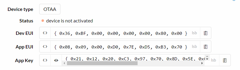
static uint8_t LORA_APP_EUI[] = { 0x08, 0x09, 0x00, 0xD0, 0x7E, 0xD5, 0xB3, 0x70 };
static uint8_t LORA_APP_KEY[] = { 0x21, 0x12, 0x20, 0xC3, 0x97, 0x70, 0x8D, 0x5E, 0x64, 0x20, 0x0E, 0x9C, 0xFC, 0x6C, 0x3F, 0xCF };
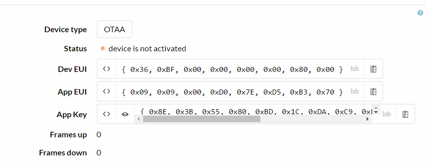
static uint8_t LORA_DEVICE_EUI[] = { 0x36, 0xBF, 0x00, 0x00, 0x00, 0x00, 0x80, 0x00 };
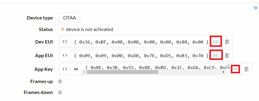
Which should match this TTN OTAA setup:
++++++++++++++++++++++++++++++++++++++++++++++++
Also commented out s1143
+++++++++++++++++++++++++++++++++++++++
void Application::configureSensors(){
max44009->init(config->getMAX44009_MODE());
bme280->init(config->getBME280_MODE());
mpu9250->init(config->getMPU9250_MODE());
// si1143->init(config->getSI1143_MODE());
gpsSensor->init(config->getuBlox_MODE());
++++++++++++++++++++++++++++++++++++++++++++++++++
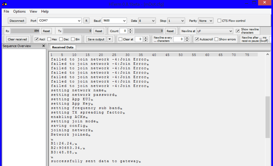
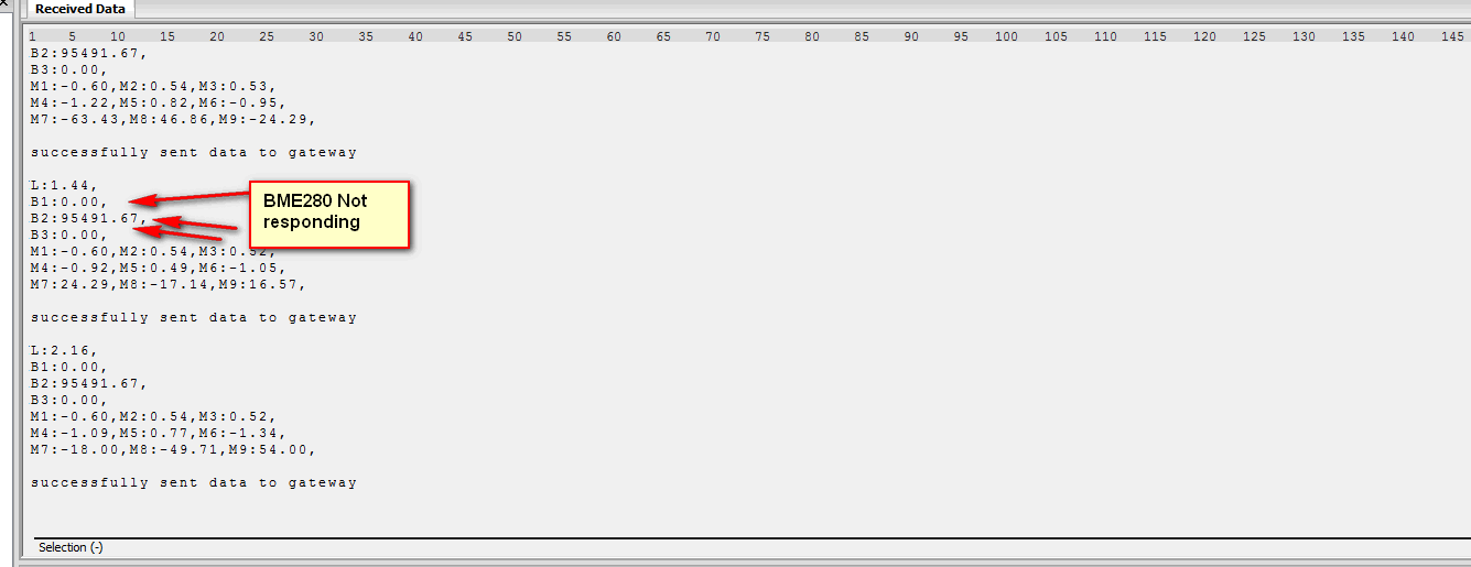
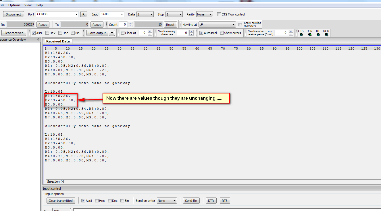
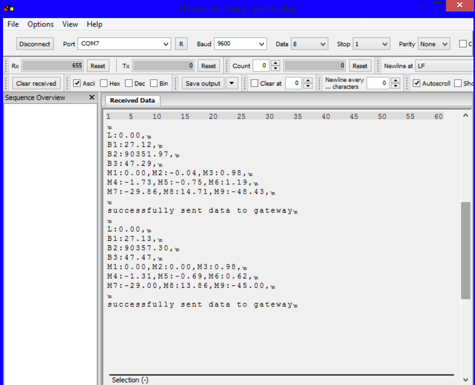
When I run this I get two incorrect behaviors:
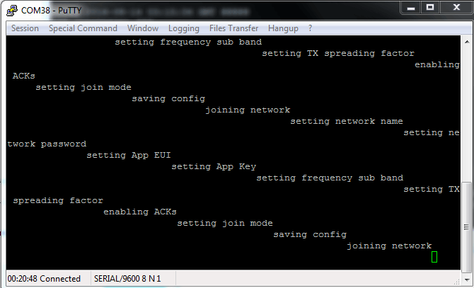
a) In the COM Window (serial to STLink Virtual COM Port) I see this upon startup…
The node does NOT join the network as evidenced by:
the message in above picture ‘Device is Not Activated’ (as well as the keys have not been generated
and
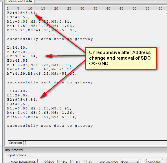
b) and the text is wrapped… (I am connected 9600)
What do I have misconfigured…
Thank you for your assistance…
 .
.