Dear @leo_korbee and @cslorabox,
thanks a lot for the replies, remarks and experiments. Most probably I compared apples and oranges. I did not check the differences between the STM32F103 and STM32L051C8T6 - shame on me.
Anyway, thanks a lot for the support; I really appreciated. I should continue with the appropriate micro controllers.
Dear all,
in the meantime I could obtain a STM32L051C8T6 . I also used the code provided by @leo_korbee. Thanks to the detailed README I could run the code in platformIO, added the custom board (adopted the minipill_l051c8_lora.json file) and I can “talk” to the STM32L051C8T6. There is one little problem on which I am working the last days: The I2C bus.
I did all the steps, most probably not correct, according to https://github.com/stm32duino/wiki/wiki/Add-a-new-variant-(board). Thanks to the existing custom board, which is provided in the gitlab repo, I started with these files and added the “missing” parts for I2C, which were generated by the STM32CubeMX code after having setup the STM32 and configured the pins appropriately. Comparing the variant files yields:
ldscript.ld is the same
PeripheralPins.c:
in WEAK const PinMap PinMap_I2C_SDA changed the pin to PB_7 and commented out the others (PB_9, PB_11, PB_14)
WEAK const PinMap PinMap_I2C_SCL[] changed the pin to PB_6 and commented out the others (PB_8, PB_10, PB_13)
commented out the pin PB_6 in WEAK const PinMap PinMap_UART_TX[]
commented out the pin PB_7 in WEAK const PinMap PinMap_UART_RX[]
variant.cpp - changed the WEAK void SystemClock_Config(void) according to the main.cpp file generated by STM32CubeMX, i.e.
The result that I can see the I2C clock and some data measured by an oscilloscope. However, the data seems to be cut, the data is too short. Does anybody have an idea how why this happens or how to activate the I2C bus?
Dear @pallago,
I already wanted to test the I2C functionality on the MiniPill LoRa, so you gave me a little push. I applied the changes you did, and got at first attempts the same results, or actually no data/clock at all. I did the same test on the STM32F103 (BluePill), with the same result. Then I realised that you have to apply a 10k pull up resistor on the SDA and SCL line, because it is a bus protocol. I got correct I2C signals. Finally I read the data of a TCN75A temperature chip as a test It worked great!. Soon I will update my repository on the MiniPill LoRa.
Regards, Leo.
Thanks again @leo_korbee. I try to communicate with an OLED display via I2C. Using the BluePill the communications perfectly but I struggle a lot with the STM32L051C8T6. (I used the same code.)
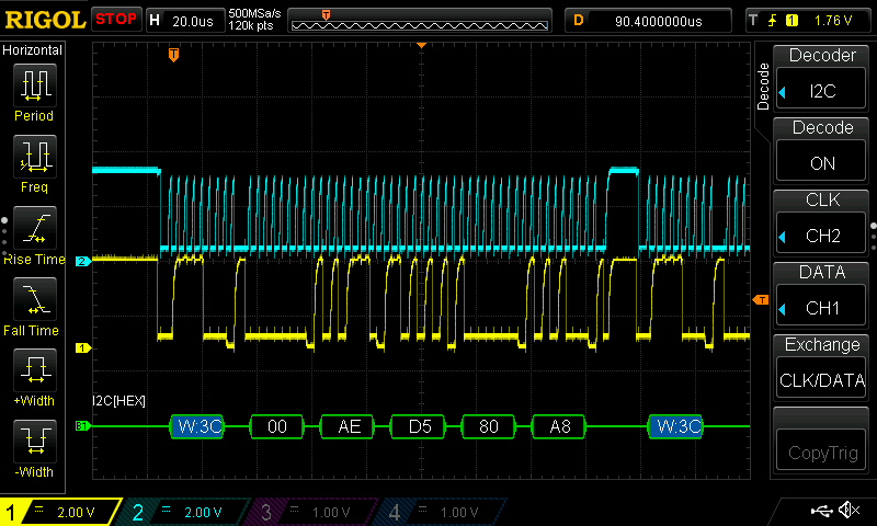
Here is a screenshot of the scope with the BluePill (blue CLK, yellow SDA).
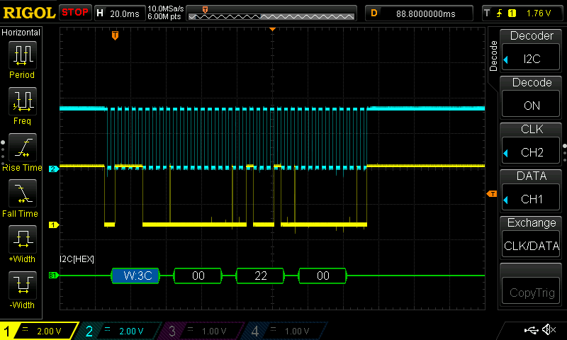
And another one with the STM32L051C8T6 (compare timing: us and ms)
I think I imagined everything too easy; I must look more deeply into the code(s) and figure out why the Bluepill period is us meanwhile for the STM32L051C8T6 it is ms, a factor 1000 slower. I did definetly something wrong.
Probably wrong clock divisors. Are you running the L0 off the clock PLL like a conventional STM32, or are you using the internal low power clock that runs just over 2 MHz? Most LoRaWAN nodes would do so, unless they needed to operate the USB capability of the family members that have that.
But I2C actually should work even drastically underclocked.
Hello @pallago,
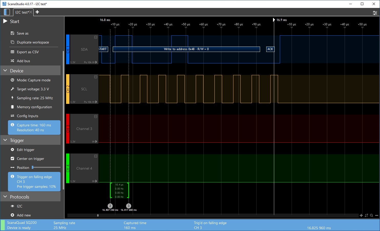
In the test I did with your changes in the variants files I also got 10 ms clock signal instead of us. I updated the variants files with minimal changes to support I2C and updated the git repository. I think the clock changes you added to the variant.cpp are the cause of this behaviour. In my tests with the new variants files I get a I2C clock of 100kHz (10us).
@pallago: I have reproduced your problem with a OLED SSD1306 128x32 with Adafruit drivers. The problem seems indeed the clock config. I leave the variant.cpp as it is for reduction of power as @cslorabox mentioned.
For testing you can put SystemClock_Config(void) function generated by CubeMX in your code and call it in the first line of the setup function. This works fine for me.
I do not usually use OLED displays, when used frequently/constant they burn-in the display.
Thanks for you remarks, I’ve learned again about the clock settings and use of I2C.
With regards.
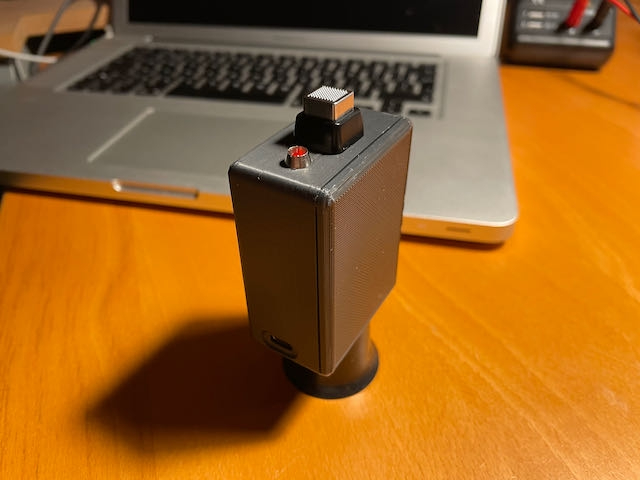
LoRa Button
With the MiniPill LoRa I have created a node with button activation. Basically it goes into deepsleep forever and is activated by external interrupt (button). It is also possible to combine timed interrupt and button interrupt. Check out https://www.iot-lab.org/blog/566/. There are two code examples available.
MiniPill LoRa and ATtiny84 node ready for The Stack V3
For the folks who want to switch to The Things Stack V3, I’ve made a blog on how to do the switch with these nodes. It can be done with the LMIC library, both OTAA and ABP or a proprietary LoRaWAN library and ABP only. The blog also describes the use of a proprietary “TinyLoRa” kind of library for a ATtiny84 controller (8K of flash).
The issue of TinyLoRa has already been discussed in the context of the new v3 stack and a ‘compromise’ based on the potential lifespan of such devices is largely settled.
So sorry but not sorry. This is the worst sort of hack. Mostly because if the stack doesn’t happen to send the downlinks as you expect, it will be stuck with trying repetitively. And as the deployment of devices continues, ADR becomes more important, so being able to handle actual downlinks is a good thing.
As someone would have to retrieve their ATtiny device to update its firmware with this new code base, for a modest sum they could swap it over to to a Pro Mini, reuse the radio & I can show them how to use the MCC LMiC 3.3 stack that will allow OTAA as well as ABP and process downlinks.
Plus, for your MiniPill, if you have a whole STM32, why use LMiC1.6 which is years out of date, when you have access to MCCI LMiC, a stack that is striving for LoRaWAN compliance?
I appreciate this is a well intentioned effort, but for the end goals of moving TTN to a more robust, resilient and technically correct system, IMHO this is not the right way to do it.
Plain and Simple LoraWan (LowPower) Library for STM32
I have made some example project with a new library to keep code simple and to reduce power as much as possible. I am testing now with CR2032 and LR44 batteries. Sleep current is about 1.4uA without sensor and 2.4uA with BME280 sensor. Transmit power is reduced and also the (sleep) power during RX1/RX2 window.
Results of the batteries test will be published as soon as the batteries are depleted. Here is the article already: https://www.iot-lab.org/blog/1088/
Plain and Simple LoraWan (LowPower) Library for STM32 (update)
The previous post was accidentally deleted. Time for an update
I have made some example project with a new library to keep code simple and to reduce power as much as possible. I am testing now with CR2032 and LR44 batteries. Sleep current is about 1.4uA without sensor and 2.4uA with BME280 sensor. Transmit power is reduced and also the (sleep) power during RX1/RX2 window.
Thanks Moeen, for your remarks. Indeed I have not added a power circuit/regulator to minimize the components/const. However I will look for improvements on that. For the reference value, I solve this by recalculation on the backend. I get the battery/vcc value, so that is the reference.
After a few years and a lot learned on coding I have major updates on my Plain and Simple LoRaWAN Library (PSLL). Now working much better. Using RSSI for randomizing for devnonce and using the RX1 time during join for calibrating internal clock. I do not use a crystal, so minimal components for my node.
More information here: https://www.iot-lab.org/blog/1209/
Have fun and enjoy!
Thanks. I think you mean save the session is a method that saves join and packet number information in non volatile memory, when the power fails, it will keep on going without rejoin. Well no, that is not available in this library. I did not needed that, as nodes keep on working for five+ years on LS14500 batteries. Why not RadioLib, well I wanted to understand and use readable code with multiple files for multiple layers of the protocol. And years ago I came across a basic library and I used it and enhanced it for my specific needs.
 . I also used the code provided by
  It worked great!. Soon I will update my repository on the MiniPill LoRa.