Hi,
Could anyone let me know what will happen inside End Node software after getting EV_TXSTART?
Why it fails, EV_JOIN_FAILED? What did my End Node miss?
Hi,
Could anyone let me know what will happen inside End Node software after getting EV_TXSTART?
Why it fails, EV_JOIN_FAILED? What did my End Node miss?
Seems very strange as you say that downlinks work for ABP.
The only other possibility is overload - how far apart is the device & the gateway?
Try or look at this code https://github.com/m2mlorawan/NodeSketch/blob/master/Example01.ino
Uncomment and select line OTAA.
I used it to join OTAA and try downlink. Both work OK.
Somsak
Random code depending on an unidentified version of LMiC is not very helpful.
“Jumping around” from one version of software to another is not likely to lead to to success, and especially not understanding.
That said, that the “Dragino LoRa mini Dev endnode” apparently uses an ATmega328p may mean the asker is stuck with old, unmaintained versions as the maintainted MCCI LMiC often compiles too large to fit.
The EV_TXSTART event is sent just before the node uplinks, in this case a join request. It then executes the first of two precisely timed receive windows. If nothing is received there it executes the second. If nothing is received there, MCCI LMiC now generates this join specific “EV__JOIN_FAILED” event case.
Typically failures are due to the node listening at the wrong time due to timing bugs, on the wrong frequency or data rate due to regional settings bugs, the network not transmitting because the join request was invalid, the gateway not transmitting because it got the command late or is out of airtime or is flaky, the network commanding wrong settings because of regional settings issues, or the network commanding wrong frequency channel for reply because the node was so close to the gateway is leaked over onto channels other than the one it is actually on (though that’s supposed to be fixed by logic to base the reply on the strongest uplink report…)
Thanks! cslorabox,
That’s what I want to hear. There seems to be 5 possibilities we have to care when implementing
OTAA algorithm.
Typically failures are caused by :
the node listening at the wrong time due to timing bugs, on the wrong frequency or data rate
due to regional settings bugs,
the network not transmitting because the join request was invalid,
the gateway not transmitting because it got the command late or is out of airtime or is flaky,
the network commanding wrong settings because of regional settings issues,
the network commanding wrong frequency channel for reply because the node was so close
to the gateway is leaked over onto channels other than the one it is actually on (though that’s
supposed to be fixed by logic to base the reply on the strongest uplink report…)
Am I correct? So next step is how I can check each possibility, and find the root cause.
Please advise me. I’s going to be helpful for me.
And I need reliable EN software correctly applied regional settings and libraries …
Add debug output to the node to see what it actually tried in terms of receiving (though make this temporary, as the debug prints might break timing).
Look in the packet forwarder log of the gateway to see if it actually transmitted.
At an extreme, blip a GPIO on the node during the receive windows and at the end of transmit, and use a scope to compare that to the needed timing, or to the signal on the transmit LED of the gateway.
That example code is working fine with ATMEGA328 or Arduino UNO3.
Use with this LMIC https://github.com/matthijskooijman/arduino-lmic.
Hi, guys!!
Sorry for no additional information for a long time.
I could establish OTAA mode by changing libraries. I decided to use mcci-catena/arduino-lmic.
Because matthijskooijman/arduino-lmic is no longer maintained. And its site says the recommended alternative is mcci-catena/arduino-lmic.
Anyway now I can enter communication sessions with OTAA mode.
But still I have some problems.
(1)My EN is not always able to receive downlink message.
Sometimes it is able, but another time it is NOT able. Why?
Any advise I can check to let it work as I expect.
(2)I can NOT choose data rate parameter as I desire.
Here is a part of my setup() function, LMIC setting portion.
// LMIC init
os_init();

// Reset the MAC state. Session and pending data transfers will be discarded.
LMIC_reset();

// set clock error
LMIC_setClockError(MAX_CLOCK_ERROR * 20 / 100);

// Set data rate and transmit power (note: txpow seems to be ignored by the library)
LMIC_setDrTxpow(AS923_DR_SF9,13);

// TTN uses SF9 for its RX2 window.
LMIC.dn2Dr = AS923_DR_SF9;  //
Once I apply another SF value, It fails.
I’ve read on an website?? if I use bigger SF value, like SF10, it reaches further.
But I can NOT choose. Any advise to pick any SF values?
Thank you,
Downlinks are unreliable and are something you should only be using extremely rarely anyway. They can also only be transmitted down in direct response to an uplink.
The network will command the node to the best spreading factor for the situation using the ADR algorithm.
Hi, it’s getting better. I started using ADR. The OTAA behavior on my end node seems to be
more stable than before. Currently I’m struggling for downlinks.
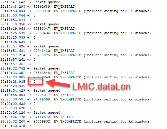
(1)My end node never receives LMIC.dataLen = 1. Why?
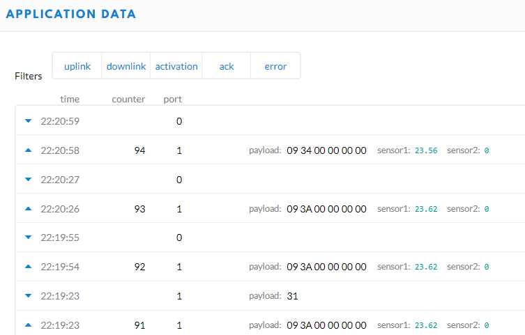
(2)TTN Application console sometimes shows strange downlinks. What’s this?
Any advice will be welcomed. Thank you.
Do you have confirmed uplinks turned on?
It’s the third parameter in the LMIC_setTxData2 function.
Confirmed uplinks are not a good thing, it requires the gateway to transmit and that means it can’t hear any uplinks.
Hi, descartes,
I don’t think it’s turned on.
Hi,
Dragino guy sent me useful information.
Debug Reference: http://wiki.dragino.com/index.php?title=LoRaWAN_Communication_Debug#Downstream_Debug
It tells me a lot of information, so seems to be very helpful.
But I don’t know how to realize.
I sent following questions to Dragino, but no response …
(1)How do I receive those messages?
Do I have to put a bunch of print statements in my sketch?
(2)Can I send AT commands from Arduino IDE serial console?
 I tried, but never sent. Those are not shown in the serial

 console and could NOT receive any responses from my

 end node.
(3)I was NOT aware of the frequency band issues. How can
I check each device, endnode and gateway and server,

supports what frequency range.
(4)I use AS923. What channel do I have to use?
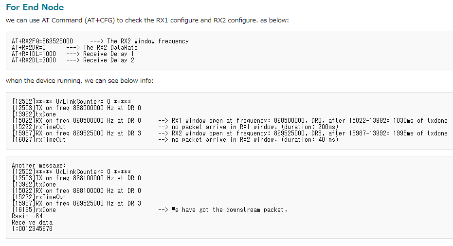
(5)Linked document stated as follows.
a) How do I know the endnode opens the receive windows correctly?

b) How do I know the downstream packet arrives at the endnode while RX1 or RX2 is open?

c) How do I know if the downstream packet matches the frequencies of the RX1 or RX2 window?

d) How do I know if the downstream packet matches the DataRate of the RX1 or RX2 window?

e) How do I know the frequencies and DataRates of the RX2 and RX1 window?
(6)How can I use AT command for LoRa mini?
Especially I want to know how to send and receive AT commands and responses.
Please help me!!
Thank you,
Hi,
According to Dragino website we can send and receive AT commands and responses.
I tried it on Arduino IDE serial console. But I could NOT send any AT commands and
could NOT receive responses from Dragino LoRa mini. How can I do that? Pease teach
me necessary hardware and software information.
Debug Reference: http://wiki.dragino.com/index.php?title=LoRaWAN_Communication_Debug#Downstream_Debug
Please do not ask the same question multiple times in separate messages on the forum.
When trying to send AT commands to the Lora board, do you have a sketch on the Arduino that sends data from the console to the Lora board and vice versa?
I don’t think so.
That’s what I want to know.
How can I implement those codes to my sketch?
Can you provide any example?
Thank you,
You are looking for a serial pass through sketch.. Make sure to use the right serial ports and baudrates.
Do I need Arduino Zero? Can I make it with Arduino Uno?