Maybe… The problem with the Uno is that it doesn’t have an available UART, so one is forced to use a software UART emulation (“SoftwareSerial”) which can be problematic in some cases.
This is why the Arduino-based TTN design used the ATmega32u4 which does have an available UART (since the PC connection is direct USB) and why its more advisable today to use an ARM-based board with at least one UART free.
(In an extremely unfortunate and poorly thought through decision, the ATmega32u4 TTN design was misleadingly named the “Things Uno” - but with such an MCU it can be no sort of “Uno” at all, approximately speaking it is a “Leonardo”)
It would appear that the “LoRa Mini” is not a typical LoRaWAN stack in a box type of device, but rather than ATmega + LoRa radio.
It should be just barely possible to run an open LoRaWAN stack on that, but you’ll be severely space constrained and have trouble fitting modern, bugfixed versions of LMiC. Some may point you to older version with known, unfixed bugs.
Really it would be better to switch to more suitable hardware based around a more capable processor.
The unfortunately mis-named Things board that is no sort of “Uno” has a module under a shield can which contains both a dedicated processor that runs the LoRaWAN stack (with AT commands) and the radio. That means the Leonardo-like ATmega32u4 only needs to issues some setup commands and pass off the data your sketch wants to send, not do any of the heavy lifting of actually implementing LoRaWAN.
Does Arduino based hardware have the same problem?
The problem is with low-resources platforms such as an ATmega328 which try to do the whole job on their own. Platforms which delegate the LoRaWAN task to its own component, or platforms with more resources (ARM or even ATmega2560-based Arduino-type approaches) don’t have the resource limitations problems.
LoRaWAN isn’t so much about needing a fast processor, as it is about needing a lot of code storage and a moderate amount of runtime storage; the ATmega328 is in modern terms rather limited in both.
Worth noting though that the next iteration of official Arduino LoRaWAN setup - the MakerWAN series - preserves the two processor idea. They really want to keep the touchy LoRaWAN stack isolated from all the issues created by user sketches.
Anyway I have to trouble shoot to complete my projects.
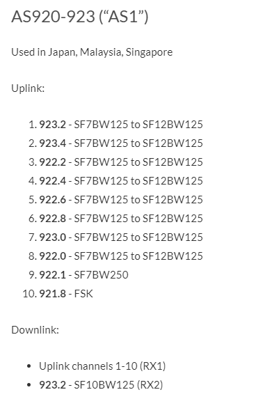
I think RX1/RX2 setting, frequency and timing, on the LoRa mini does NOT match those on my gateway. So I want to ask you :
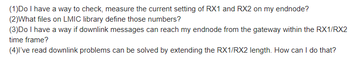
(1)Do I have a way to check, measure the current setting of RX1 and RX2 on my endnode?
(2)What files on LMIC library define those numbers?
(3)Do I have a way if downlink messages can reach my endnode from the gateway within the RX1/RX2 time frame?
(4)I’ve read downlink problems can be solved by extending the RX1/RX2 length. How can I do that?
What have you looked at? There should be no obvious reason for you to change any of the LMIC files to setup regional settings.
Please can you stop posting screen shots by default, particularly of web pages that can be linked to. If it’s a log, it should be copy & pasted as text. See here on how to format posts.
Here are three things to do:
Post a copy (as text) of your lmic_project_config.h so we can see the regional settings in use.
Set #define LMIC_DEBUG_LEVEL to 1 in config.h so you get more debug output and then post it (as text) showing from power up to join fail or downlink fail.
Post the gateway log (as text) for the corresponding time period.
Set #define LMIC_DEBUG_LEVEL to 1 in config.h so you get more debug output and then post it (as text) showing from power up to join fail or downlink fail.
This seems to be a good information for me. But I tried I got memory usage error.
I have to cut memory usage. I need time to strugle.
Anyway I think my problem was caused by downlink packet frequency and timing.
So I need following information.
(1)Do I have a way to check, measure the current setting of RX1 and RX2 on my endnode?
(2)What files on LMIC library define those numbers?
(3)Do I have a way if downlink messages can reach my endnode from the gateway within the RX1/RX2 time frame?
(4)I’ve read downlink problems can be solved by extending the RX1/RX2 length. How can I do that?
I asked several times. But nobody answered to my question. Why?
People are trying to help by providing information on how to debug your issues. The answers may not be the ones you are expecting, but they are sound.
In answer to your questions:
Yes if you know how to modify the LMIC code and connect the node to an oscilloscope. Given your questions I seriously doubt you will be able to accomplish this.
Have you searched the source code? What did you find?
That would link back to question 1.
This question is answered almost weekly on the forum. However randomly changing things in the hope it will start to work is not a sound solution. If you still want to try, add the following line at the end of your init function.
Perhaps because you, yourself, have not answered our questions: what frequency and spreading factor is your gateway actually transmitting the missed downlinks on?
As for the debug logging:
I tried I got memory usage error.
This is why trying to squeeze a LoRaWAN stack into an ATmega328 cannot be recommended
Yes if you know how to modify the LMIC code and connect the node to an oscilloscope. Given your questions I seriously doubt you will be able to accomplish this.
Have you searched the source code? What did you find?
That would link back to question 1.
This question is answered almost weekly on the forum. However randomly changing things in the hope it will start to work is not a sound solution. If you still want to try, add the following line at the end of your init function.
LMIC_setClockError((MAX_CLOCK_ERROR * 10) / 100);
(1)Oscilloscope!? Is it the only way to check them? Do you have any good documents which tells
how to do that? I expect somebody had done similar things.
You don’t have another way? like applying some debug codes in the source code and print
some values. Dragino guy told me applying AT commands. But recently he said Dragino LoRa
mini doesn’t have AT command functions …
(2)I found some information in my code. But I’m not sure these are the right part. As I said several
times. I don’t think my problems are not a special one for the experienced people. For the people
who have implemented OTAA and downlink, some people know how to solve the problems. That’s
why I’m asking for “common sense” information to solve problems.
(3)Same as above (2). Please give me “common sense”, typical, well-experienced, easy method to
solve problems. Many documents says “ABP is easy. But OTAA is trouble-some.” But I think it’s
strange nobody provides easy-to-solve documents or books, like “OTAA/downlink for Dummies.”
I’m expecting common, typical procedure how to analyze problems, adjust RX1/RX2 time-frame,
frequencies and succeed for OTAA. I’m a novice engineer. But I’m expecting genius engineers in the
world have good technique and knowledge I don’t know.
(4)Is that the only way? I tried, but no changes. And Dragino guy didn’t tell the code realizes changing
RX1/RX2 length. Is there another method to extend RX1/RX2 length?
You may want to reconsider your approach to getting volunteer engineers who give up their valuable time to answer questions.
Given all the moving parts that make up LoRaWAN, it is not as simple as creating a Dummies guide because all sorts of things could be going on.
The Dragino LoRa mini dev is basically an Arduino Pro Mini with a radio chip which is a combination I use a fair amount for appropriate applications. If you want to read this, you’ll see that it took me a while to get to grips with this hardware combination and that it does in fact work:
I think this entire thread has got in to a tailspin and about the only thing we haven’t looked at is the possibility that the hardware is compromised in some way. So rather than collectively banging our head against the wall, perhaps you could get a different device to try out - preferably one with more RAM & Flash.
One possibility is the Adafruit Feather M0 with RFM95. I know this works because I’m helping out someone on another thread (see here) so I have one on my desk working away quite happily. Note, you will need to add a connection to the board for it to work with LoRaWAN - all the details are on the Adafruit website.
Alternatively if you want to sidestep all the LoRaWAN challenges, then the Arduino MKR WAN 1310 has both a powerful processor and a dedicated LoRaWAN module that will take care of LoRaWAN code for you, but you will still need to configure it.
This is indeed a good choice, particularly as it’s the original platform used for development of MCCI LMiC. Also worth noting that they have some historic experience with Japan, and test equipment able to run closed-loop tests on the frequency plan used by one region, even while physically sitting in another. If you were using the feather & RFM95 board, issues getting it to work in Japan would be quite appropriate to raise in an issue on the github repo.
That has historically not had perfect support for all regions, so it would make sense to double check that it will actually work in Japan before purchase. In theory the LoRaWAN stack is user-fixable, in practice it’s going to be a bit more complex to do so in such context.
experienced engineers have been trying to help you. They haven’t written a dummy guide because there are different solution to different problems and documenting them all does take a lot of time for which no-one is paying.
you expect something, based on what? We are providing a free service to the community. If that service does not match your expectations, feel free to search for paid for help, don’t make your mismatched expectations our problem.
you should not need to adjust RX1/RX2 timeframe in the MCCI LMIC stack. Depending on the hardware you might have to relax the timing so your hardware listens at the right time. The only way to know for sure is to use hardware (oscilloscope) to check the timing because added debug messages using the serial port change that timing.