I did say;
"although in most cases its going to work"
I did say;
"although in most cases its going to work"
If logic converter is the reason, I suppose using a board which works on the same logic as that of lora module is better. How about Adafruit feather M0 with RFM95 lora?
If somebody can share their experience of using feather M0 with RFM95 for sending sensor data to TTN, it would be great. I’m sure the example code in Lmic library (ttn-otaa-feather-dht22) can directly be used for the purpose.
No, don’t change this topic ! you’re allready trying too hard and too long
Its years since I have bothered with 5V Arduinos, for 99.9% of modern devices you end up having to use logic level converters.
And at the SPI speeds used with LoRa devices a lot of logic level convertors are highly marginal.
Not really, even at 5.5v VIH of an ATmega is still below 3v.
That said a LoRaWAN node likely does nothing where running an ATmega at 8 MHz and 3.3v would not work.
The feather M0 probably is one of the more thoroughly supported platforms for LMiC, especially the MCCI LMiC repo (they have their own STM32 boards as well).
In contrast ESP32 is pretty much completely broken in terms of receive timing. I think ESP8266 may work, but never really tried that.
If one looks that up, it’s the following line:
static void startrx (u1_t rxmode) {
ASSERT( (readReg(RegOpMode) & OPMODE_MASK) == OPMODE_SLEEP );
Typically this indicates an SPI communication failure, but it can also be a result of unexpected program flow (ie, getting here when the radio has not actually been put to sleep). You can try temporarily commenting out the ASSERT and seeing if you get any further.
FAILURE
C:\Users\Sam\Documents\Arduino\libraries\MCCI_LoRaWAN_LMIC_library\src\lmic\oslmic.c:53
This appears to most likely result from a failure of radio_init() - probably again a communication issue, such as a wiring mixup etc.
If you are using jump wires, make sure they all have continuity, twice recently I’ve found bad ones.
Make sure MOSI and MISO aren’t swapped. Ideally look at the SPI signals with a scope or logic analyzer.
Make sure the RFM95 breakout’s regulator is giving an output.
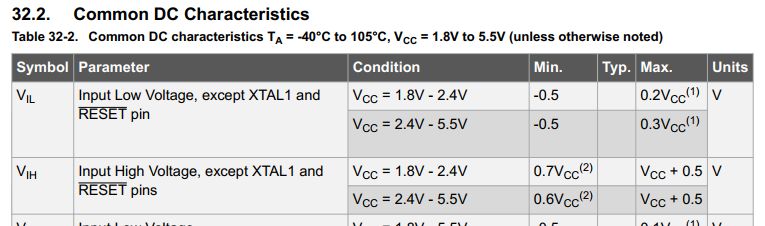
(2. “Min.” means the lowest value where the pin is guaranteed to be read as high)
At VCC = 5.5V then Vih = 5.5V x 0.6 = 3.3V ?
At VCC = 5V then Vih = 5V x 0.6 = 3.0V ?