Need help with my first TTN node

Hi TTN community,

Please help with building and programming my first TTN node.

The hardware is:

  • Arduino Uno R3
  • Adafruit RFM95W LoRa Transceiver Breakout with 868 Mhz

The IDE is Arduino v1.8.9 with newest arduino-lmic-master library installed!

I used this tutorial:
https://www.mobilefish.com/developer/lorawan/lorawan_quickguide_build_lora_node_rfm95_arduino_uno.html

This is how the circuit looks like at the moment:
TTN-Test-Node%20v1

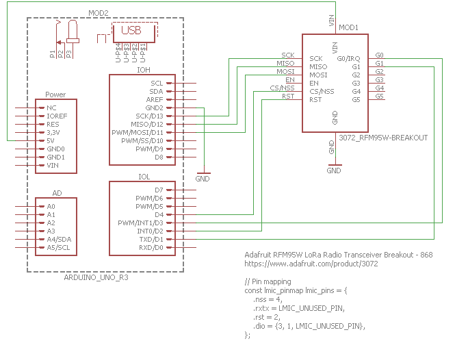
Pin mapping is in the schematics as well.

Node is registered with TTN and I tried the ttn-abp example in Debug Mode 2.

No error messages during compilation and upload.

This is what I always see in the terminal window:

08:07:58.915 -> Starting
08:07:58.962 -> RXMODE_RSSI
08:07:58.962 -> 78: irq: dio: 0x1 flags: 0x0
08:07:58.962 -> 114: Scheduled job 0x25d, cb 0 ASAP
08:07:58.962 -> 184: Cleared job 0x25d
08:07:58.962 -> 401: engineUpdate, opmode=0x808
08:07:58.962 -> 472: Uplink data pending
08:07:58.962 -> 605: Considering band 0, which is available at 398
08:07:59.009 -> 876: Considering band 3, which is available at 0
08:07:59.009 -> 1141: No channel found in band 3
08:07:59.009 -> 1311: Considering band 0, which is available at 398
08:07:59.009 -> 1594: No channel found in band 0
08:07:59.009 -> 1763: Considering band 1, which is available at 398
08:07:59.009 -> 2040: Airtime available at 398 (channel duty limit)
08:07:59.009 -> 2315: Ready for uplink
08:07:59.009 -> 2847: Updating info for TX at 471, airtime will be 3856. Setting available time for band 1 to 3826712576
08:07:59.009 -> 3099: TXMODE, freq=867300000, len=26, SF=7, BW=125, CR=4/5, IH=0
08:07:59.009 -> Packet queued
08:07:59.009 -> 3202: irq: dio: 0x1 flags: 0x0
08:07:59.056 -> 3371: Scheduled job 0x25d, cb 0xf11 ASAP
08:07:59.056 -> 3584: Running job 0x25d, cb 0xf11, deadline 0
08:07:59.056 -> 3830: Scheduled job 0x25d, cb 0xf24 at 62869
08:07:59.056 -> 4073: irq: dio: 0x1 flags: 0x0
08:07:59.056 -> 4235: Cleared job 0x25d
08:07:59.056 -> 4295: Scheduled job 0x25d, cb 0xf24 ASAP
08:07:59.056 -> 4513: Running job 0x25d, cb 0xf24, deadline 0
08:07:59.056 -> FAILURE
08:07:59.056 -> C:\Users\gknese\Documents\Arduino\libraries\arduino-lmic-master\src\lmic\radio.c:660

Please help

Kind regards
Gerd Knese

You have DIO1 on the RFM95 connected to the TXD pin on the UNO, thats used by the UNOs program uploader and for sending output to the serial monitor.

Put DIO1 on an unused pin.

1 Like

Hi LoRaTracker,

Uh, yes you are fully correct.

I changed this to D5 and itā€™s running now.

Thanks a lot
Gerd

Wise to start on the assumption that the tutorial is correct, it had DIO1 connected to pin 5.

Fully correct, but sometimes we lose sight of the wood for the trees. I started with the Adafruit tutorial first and mixed them up.
Big mistake! :rofl:

Iā€™m using the same hardware, and tried the revised schematic (G1->D5). Had uploading issues when used 5V on Uno (not sure if I have made any mistakes) but successfully tested by changing it to 3.3V. I ran the ttn-otaa example of ā€œHello Worldā€, I could connect to TTN and could see the data in TTN console (this is definitely a big achievement for me because Iā€™ve been unsuccessfully experimenting different hardware over the past few weeks).

I wanted to make an incremental step, and I tried to send DHT11 data to TTN. Iā€™ve used this sketch: https://github.com/robertlie/dht11-ttn-rfm95/blob/master/sketches/ttn-otaa-dht11/ttn-otaa-dht11.ino. Got compiled, and uploaded, but I could see nothing in the serial monitor, except ā€˜Startingā€™. Iā€™ve tried DHT example from TTN library as well, but no luck. It says ā€œNo status, no response from RN moduleā€. Can somebody please provide a working sketch. Many thanks in advance.

Received Adafruit RFM95 breakout board and connected it to Arduino Uno. Successfully ran the ttn-otaa LMIC sketch to send Hello World message to TTN. However I could not modify the sketch to be able to send sensor data (for example DHT11) to TTN. Spent couple of hours, looked at many resources, but was unsuccessful. Tried this one: https://github.com/robertlie/dht11-ttn-rfm95/blob/master/sketches/ttn-otaa-dht11/ttn-otaa-dht11.ino. Lmic library has an example for ttn-otaa-dht22 for feather; tried to adapt it to Arduino, but even then no luck.

Somebody please help me with the first lora node. I know that its just a minor tweak, but not able to do that, because I donā€™t have any prior programming experience. Should I explore any other libraries (for example one wire library). Any help is greatly appreciated.

what gateway are you using ?

Its helpful to the forum if you tell us what the actual problem you had was.

However I could not modify the sketch to be able to send sensor data (for example DHT11) to TTN.

Did you get compile errors, or did it appear to work, but no data recieved in TTN or what ?

Lmic library has an example for ttn-otaa-dht22 for feather; tried to adapt it to Arduino, but even then no luck.

So what was the problem here ?

Imst ic880a + Pi 3 (868mhz)

In all cases (Robert lie code, adaptation of otaa-dht-feather code), the code gets compiled and gets uploaded successfully. Upon opening serial monitor, it says ā€˜Startingā€™, and then nothing happens after that.

pinmapping could be wrongā€¦ this part of the sketch, check that first

// Pin mapping
const lmic_pinmap lmic_pins = {
.nss = 10,
.rxtx = LMIC_UNUSED_PIN,
.rst = 5,
.dio = {2, 3, LMIC_UNUSED_PIN},
};

Could well be a pin mapping issue, as @BoRRoZ suggested.

One test, is to deliberatly change say the .nss pin to a ā€˜wrongā€™ pin and see if the error is the same.

Iā€™ve double checked the pin mapping (w.r.t schematic) and its correct. As I said before, I used the corrected form of the circuit mentioned in post#1. In addition Iā€™ve interfaced DHT11 sensor to the circuit. The pin mapping in my case is as follows:

// Pin mapping
const lmic_pinmap lmic_pins = {
.nss = 4,
.rxtx = LMIC_UNUSED_PIN,
.rst = 2,
.dio = {3, 5, LMIC_UNUSED_PIN},
};

I ran both the sketches again, and I see the same ā€˜Startingā€™ in case of robertlieā€™s sketch, and ā€˜Start?pā€™ in case of ttn-otaa-feather sketch. And nothing happens after that.

Iā€™ve tried @LoRaTrackerā€™s suggestion as well. The following is the output on serial monitor in that case:
Starting
FAILURE
C:\Users\Sam\Documents\Arduino\libraries\MCCI_LoRaWAN_LMIC_library\src\lmic\oslmic.c:53

I realized something, my node is connected to TTN as I could see the status ā€˜xā€™ minutes ago, which is altogether a new development. I could also see devadd, appeui and deveui (just once) in the Data tab. However Iā€™m not sure which of the two codes partially worked (in the sense connected to TTN)

Donā€™t know whatā€™s happening.

Adafruits tutorial code for their board includes checks to see if the board is responding correctly (i.e. that its connected correctly) did you try that code ?

Can you please send the link?

By any chance, is it because Iā€™m not using logic converter (Iā€™m using G1 pin of rfm95 breakout)? But there were no issues when I was sending Hello World message to TTN.

Sorry if my questions/comments seem to be too dumb, Iā€™m completely a novice in IOT and LoRaWAN.

I found it via a Google search.

That breakout board does not have logic level converters on the RFM95 DIO pins, and it should really as even if the respective voltage regulators are exatly 3.3V and 5V, its marginally out of specification, although in most cases its going to work.

If the 3.3V regulastor is slighty low and the 5V regulator is slightly high then a logic level converter may be required.

However if the hello world example worked, you migh conclude that its not a logic level conversion issue.

Its also worth mentioning that the Adafruit board does not have input protection on DIO2, this pin can be used on the RFM95 as an input, so feeding 5V into it may not do the RFM95 a lot of good.

Thanks for your inputs. Do you mean to say that Iā€™ll have to use logic converter to make the board work?