Please don’t do that, it’s impolite usage of the band.
I know it’s impolite usage but it is just for academic purposes. Thanks anyway.
It may be that we have brought you some confusion in the representation of the frequency band. In fact, the 868MHz version can work normally between 863 ~ 870MHz. We intentionally made the bandpass during debugging.
Thanks, but I think you did’nt understand my question. I would like to know how to select the exact frequency the packet is sent in the 868 band. For example, I want to send a packet always in the frequency 868.1MHz although I know it is transmitted in a pseudo random secuence of frequencies. By this way, I would be able to separate the channels depending on the node.
My scenery is the following one:
Node A: always TX in 868.1MHz
Node B: always TX in 868.3MHz.
Node C: always TX in 868.5MHz.
Thanks!
That is really NOT how LoRaWAN works.
LoRaWAN tells nodes apart by headers prefixed in the message. And since LoRaWAN operates on a shared band, collisions are assumed to come from other people’s usage not just your own devices.
LoRaWAN operates on randomized spread in time and frequency.
TTN is a LoRaWAN network.
And this is the TTN Forum.
Great review from Andreas Spiess
2 Likes
The board looks promising but like Andreas concluded, it definitely needs (better) documentation.
1 Like
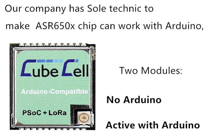
Heltec’s CubeCell module is sold in two different versions.
- ‘No Arduino’ without Arduino support.
- ‘Active with Arduino’ with Arduino support (more expensive).
[Updated]
According to the CubeCell AT Command User Manual (v0.2) Arduino support is activated by entering a serial key. CubeCell modules that come with Arduino support are factory activated.
Modules that come without Arduino support have the option to activate it later by entering a serial key via AT commands (presumably the keys can be purchased from Heltec separately).
1 Like
When is availability of PlatformIO support expected?
1 Like
The 433 MHz version seems to be the board to go for FossaSAT-1b reception on 436.7 MHz next spring. 
@bluejedi
We are busying update the document page recently, hope the English document page can be done this week.
PlatformIO is in testing now, I think we will be able to release at the end of January.
2 Likes
for all playing with the CubeCells:
1 Like
Nice respository, you know of any that has implemented the DS18B20 to the cubecell?
BR
/A
The OneWire library found in the official repository is broken, hope to find time this weekend to get it running again.
Hi,
I used to be able to compile this code very well. But recently I get all kinds of error messages. Like
Multiple libraries found for “LoRaWan_APP.h”
Used: /Users/andre/Library/Arduino15/packages/CubeCell/hardware/CubeCell/0.0.4/libraries/LoRa
and
/Users/andre/Library/Arduino15/packages/CubeCell/tools/gcc-arm-none-eabi/8-2019-q3/bin/…/lib/gcc/arm-none-eabi/8.3.1/…/…/./arm-none-eabi/bin/ld: /Users/andre/Library/Arduino15/packages/CubeCell/hardware/CubeCell/0.0.4/cores/asr650x/projects/CubeCellLib.a(AT_Command.o): in function
printDevParam': E:\lib/AT_Command.c:1229: undefined reference toKeepNet
what am I doing wrong, or what’s changed?
UPDATE: For now the problem is solved by using CubeCell board Framework 0.0.3 and not version 0.0.4.
Thanks for your CubeCell information on GitHub.
“Best obtained” in what configuration?:
- Powered by Li-ion battery via battery connector, USB or external supply via 3.3V pin?
- Was that with or without AT command support enabled?
IIRC I read somewhere that the 3.5 μA in sleep mode is when externally powered via 3.3V pin (e.g. powered directly from LiFePO4 battery).
@andreas58 please use the github version.
that version will always contain all bug fixes.
the library manager version is outdated.
@bluejedi. Hi thanks for your comments . The test was carried out with a working Script and a BME680 sensor powered via Vext, sending every 15 minutes,with no AT support or USB connected. This showed 20 μA current was when the node was in its sleep cycle and with a much higher level when powering sensor RX or TX. The Power was only supplied by 3.7v Lipo-ion battery connect though the battery connector. If you use USB it will be Higher and if charging etc… I would note that when powered from a 3.3v supply then you can get around 4μA, Please dont connect directly a battery to the 3.3 v rail as may cause damage.
I have a battery life calculatator on my web site in downloads to workout battery life based on the consumprion by, sensor,RX, Dwell Time ,TX , SF, Duty cycle etc. It is here https://securethings.uk/sdm_downloads/lorawan-energy-calculator.
I have heard that some people have got arround 10μA, But I do not know what their settings were let me know if you get it that low.
Simon
Directly connecting a 3.2V LiFePo4 battery should be possible voltage-wise.
Is there any other reason than voltage (or reverse polarity) that may cause damage?
I’m trying to understand the missing pieces of the ‘Power management system’ part in the HTCC-AB01 diagram to find out how to properly connect power to the board (and how not) in order not to damage it. There are Vusb, Vin, Vs(olar), VDD and Vext and their relation and what can and cannot be connected at the same time does not become clear from the circuit diagram (because parts are missing).
E.g. is it safe to connect USB and Vin at the same time?, is it safe to connect USB and a solar panel at the same time? Are these protected by the ‘power management and charging system’ or not? This does not all become clear from the diagram and documentation.
In the HTCC-AB01 circuit diagram some essential parts of the ‘Power management system’ are only represented by ‘functional blocks’ (black boxes) which hides their actual implementation. 
The diagram shows that:
- Vin is directly connected (via fuse) to USB power. The board should therefore be powered either via USB or via Vin but NEVER both.
While trying to figure out how things are connected I noticed that:
- Vin is connected via Schottky diode (D4) to pin VS (Vsolar).
VS is the input pin for connecting a solar panel and serves as input for the battery charger chip.
When both a solar panel and Vin or USB are connected, current may flow from Vin to the solar panel (which the panel normally ‘will not like’).
To protect the solar panel from possible reverse current, it should be connected to pin VS with an external (Schottky) diode in series. That diode is not provided in the ‘Charging management system’ and is not integrated on the board.