Node based on Raspberry?

Hi @wklenk,

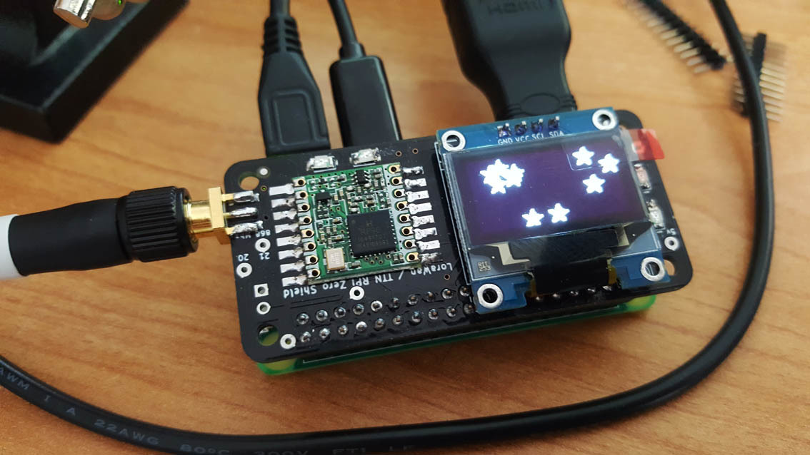
Thank you very much for your Dragino LoRa/GPS HAT Hardware Abstraction Layer for the IBM LMIC library.

I’m trying to use it on my rPi 3 and Dragino HAT but I encounter some problems

I thing I have all prerequisites to run your Hello example but unfortunately it doesn’t work :smirk:

# ./build/hello.out
000000000 HAL: Initializing ...
000000001 HAL: Set radio RST pin to 0x00
000000001 HAL: Wait until 000000002 ms
000000002 HAL: Set radio RST pin to 0x02
000000002 HAL: Wait until 000000007 ms
000000008 HAL: Failed. Aborting.

I’m suspecting a pin problems …

I hope, you (or someone else here :blush:) can help me to get it work.

Here is an output of gpio readall just a reboot :

 +-----+-----+---------+------+---+---Pi 3---+---+------+---------+-----+-----+
 | BCM | wPi |   Name  | Mode | V | Physical | V | Mode | Name    | wPi | BCM |
 +-----+-----+---------+------+---+----++----+---+------+---------+-----+-----+
 |     |     |    3.3v |      |   |  1 || 2  |   |      | 5v      |     |     |
 |   2 |   8 |   SDA.1 | ALT0 | 1 |  3 || 4  |   |      | 5v      |     |     |
 |   3 |   9 |   SCL.1 | ALT0 | 1 |  5 || 6  |   |      | 0v      |     |     |
 |   4 |   7 | GPIO. 7 |   IN | 0 |  7 || 8  | 1 | ALT5 | TxD     | 15  | 14  |
 |     |     |      0v |      |   |  9 || 10 | 0 | ALT5 | RxD     | 16  | 15  |
 |  17 |   0 | GPIO. 0 |   IN | 1 | 11 || 12 | 0 | IN   | GPIO. 1 | 1   | 18  |
 |  27 |   2 | GPIO. 2 |   IN | 0 | 13 || 14 |   |      | 0v      |     |     |
 |  22 |   3 | GPIO. 3 |   IN | 0 | 15 || 16 | 0 | IN   | GPIO. 4 | 4   | 23  |
 |     |     |    3.3v |      |   | 17 || 18 | 0 | IN   | GPIO. 5 | 5   | 24  |
 |  10 |  12 |    MOSI | ALT0 | 0 | 19 || 20 |   |      | 0v      |     |     |
 |   9 |  13 |    MISO | ALT0 | 0 | 21 || 22 | 1 | IN   | GPIO. 6 | 6   | 25  |
 |  11 |  14 |    SCLK | ALT0 | 0 | 23 || 24 | 1 | OUT  | CE0     | 10  | 8   |
 |     |     |      0v |      |   | 25 || 26 | 1 | OUT  | CE1     | 11  | 7   |
 |   0 |  30 |   SDA.0 |   IN | 1 | 27 || 28 | 1 | IN   | SCL.0   | 31  | 1   |
 |   5 |  21 | GPIO.21 |   IN | 1 | 29 || 30 |   |      | 0v      |     |     |
 |   6 |  22 | GPIO.22 |   IN | 1 | 31 || 32 | 0 | IN   | GPIO.26 | 26  | 12  |
 |  13 |  23 | GPIO.23 |   IN | 0 | 33 || 34 |   |      | 0v      |     |     |
 |  19 |  24 | GPIO.24 |   IN | 0 | 35 || 36 | 0 | IN   | GPIO.27 | 27  | 16  |
 |  26 |  25 | GPIO.25 |   IN | 0 | 37 || 38 | 0 | IN   | GPIO.28 | 28  | 20  |
 |     |     |      0v |      |   | 39 || 40 | 0 | IN   | GPIO.29 | 29  | 21  |
 +-----+-----+---------+------+---+----++----+---+------+---------+-----+-----+
 | BCM | wPi |   Name  | Mode | V | Physical | V | Mode | Name    | wPi | BCM |
 +-----+-----+---------+------+---+---Pi 3---+---+------+---------+-----+-----+

SPI is activated with raspi config here is an lsmod output :

Module                  Size  Used by
evdev                  11396  2
brcmfmac              186403  0
brcmutil                5661  1 brcmfmac
cfg80211              428871  1 brcmfmac
rfkill                 16037  2 cfg80211
hid_apple               4925  0
spi_bcm2835             6678  0
i2c_bcm2708             4834  0
bcm2835_gpiomem         3040  0
bcm2835_wdt             3225  0
uio_pdrv_genirq         3164  0
uio                     8000  1 uio_pdrv_genirq
i2c_dev                 5859  0
ipv6                  347556  32

I just have a doubt about spidev I don’t know how to activate it, a modprobe spidev do nothing …

Wiringpi and bcm2835 are installed too.

Thanks for your help :slight_smile:

Regards

I’m currently testing my RPi Zero W TTN Shield

More on:

3 Likes

@itacos did you got it working?

Yes. Working perfectly. 1 week uptime now with no issue.

2 Likes

Hello,

After some advanced tests, i can say that joining with OTAA and transmit data on my gateways works.

Sometimes, some segmentation faults occurred, randomly at the begin or after some minutes of execution, but I did not identified the root cause yet.

1 Like

Hi Wklenk,
thanks for your awesome solution . I tested the code you provided and the uplink tx seems to work perfectly( I could test only the uplink since my gateway is a single channel based on the modified version of the dual_chan_pkt_fwd). However, my single channel gateway offers a function to send downstream data.
I would like to test is with your implementation of the LMIC v1.6 using the ABP activation method. The point is that I want to send downlink data to my node ( running your software) at a random time and see if the node receives the data. I wanted to modify the periodic example so that it uses the APB method to send data to my local server over my gateway. Can you please guide me on this?

Hi,

some clarifications first:

  • Whether you use OTAA or ABP for activation does have nothing to do with sending download data. It is just the method how to “join” the network. The examples I provide use OTAA. First task would be to get them working using ABP.
  • You cannot send “data to your node at a random time”. With LoRa Class A devices, you can only receive data after you have sent data. But let’s say you get the “periodic” example running with ABP, e.g. sending some dummy data every 5 minutes, and you manage to send something back in the TTN backend, then it should be possible to receive data.
  • But I have made bad experiences with these “single channel” gateways. Are you really sure that it supports downlink messages?

Thanks for your prompt reply and also thanks for the clarifications.
The issue is that I tried your LMIC v1.6 code on my Lora Node (RPI+Dragino) and my gateway based on the same components as my node runs the dual channel packet forwarder from (https://github.com/bokse001/dual_chan_pkt_fwd).
During the test, I realized that server replies to uplinks message but my node never receives them.
Since it is a thesis project, I wanted to make sure that it is not possible to send downlink messages using the RPI+DRAGINO HAT as the gateway. I would like to have your advice on this. That is why I have the following questions:

Q1- Is it possible to have uplink and downlink message on a single channel gateway sending in both directions on the same frequency ( e.g 868.1) and also configuring the client to send then listen on the same frequency?

Note: It is obviously far from being LoRaWAN compliant

I have not been able to get this to work with the Raspberry Pi 3 B+ (esp. for the US). I have it running, but it doesn’t show up in the TTN console (never seen). I did the following:

  1. Change config.h to have: #define CFG_us915 1
  2. Change line 764 of lmic.c to LMIC.channelMapp[channel/16] &= ~(1<<(channel&0F));
  3. Added in all session keys, eui’s and dev address.

Also doesn’t show up in gateway traffic, though it is running.

What am I missing?

hello melvin i have always the same probleme with the 0h0h Unknown interrupt flags for Fsk, did you find the solution? and i’m trying to send the message with boucle while did you get it? because once i made run the message will be sended juste one time .

thank you

you realize that this topic is 2 years old ??

[0#90]

i know but i didn’t find another example to send message to the things network. can u help me plz if you know or have an idea.

thank you

start searching this forum