Hi all,
I’m trying to create a node with an ESP8266 (Feather Huzzah from Adafruit) and a RFM95W. Does anyone know if this is possible and how? I also have a RN2483 but the RFM95W is much smaller…
Thanks in advance!
Rene
Hi all,
I’m trying to create a node with an ESP8266 (Feather Huzzah from Adafruit) and a RFM95W. Does anyone know if this is possible and how? I also have a RN2483 but the RFM95W is much smaller…
Thanks in advance!
Rene
The RN2483 is easier to use - you just need serial to talk to it. The RFM95W will need a whole LoRaWAN stack implementing on the ESP8226.
Andrew
Ok, yes I found that already. However, it is quite a bit larger and how about battery usage. Does it compare to the RFM95W? And is there a LoRaWan stack available for ESP8266 right now?
Best, Rene
Well @popcorn seems to have been busy with this. I’m also curious about the latest state of this project 
After having a second look the project seems to have gone the RN2483 route also.
It would be nice to create a node based on a cheap SX127x board like this and an ESP8266. That would be possible for less than $10 (as is mentioned in the wiki, but we still have to prove it  ourselves)
current consumption RN2483 in sleep mode 
Looks like this guy has a working ESP8266 and LoRa module combination:
And if you need a gateway take a look at this github:
cheap ESP board and serial interface
Hey, is that a lot of consumption or not? Don’t really know much about that;-)
no that’s not (compared to a ESP8266 in sleepmode)
the RN2483 need an external MCU to send serial commands, so it depends
(i am testing an attiny85 in sleepmode connected … just for on/off signalling things)
Looks interesting, you expect this to give the lowest power consumption? Indeed with ESP8266 it will probably be hard to reach very low power levels and run for months on 1 battery?. It seems the ESP32 will have some better low power features?
Besides low power consumption a low price is also interesting of course ![]() , in that regard an ESP8266 together with a SX127X board would probably beat most other combinations? (as you need a more powerful uP to implement the LoraWAN stack and need some GPIO ports for attaching sensors.
, in that regard an ESP8266 together with a SX127X board would probably beat most other combinations? (as you need a more powerful uP to implement the LoraWAN stack and need some GPIO ports for attaching sensors.
I’m still wondering how to use all these GPIO’s on the RN2483 in a usefull way. AFAIK you won’t be able to do anything like SPI, I2C, 1-Wire etc. So I guess it is mostly limited to reading on/off values and flashing LED’s or driving a single on/off output and you will need to have the more powerfull “protocol” ports of your uP to do things like that?
I am guessing microchip are thinking something like lets not try to be the cheapest solution but lets be the easiest whole cost solution. As a pre-verified module the RN2843 is probably going to save you a lot of money on the product RF verification stage, maybe it’s 5-10K savings. So they probably figure that’s a lot of sensors you need to catch up if you use a cheaper non-verified module where you have to implement and verify the stack. So that’s something like a 1000 sensors your going to need before you compete with their more expensive but ‘gold standard’ sensor.
By making the serial GPIO on the device you can just bind a very low cost microcontroller to add some application logic ( even a 10F family ) for just a few cents and use the GPIO on the RN2843 to read and write IO for “Sleepy” sensors. ie the low bandwidth sensors they consider to be their sweet spot.
In the future I wouldn’t be surprised to see them also allow programming of the onboard PIC18F46K22 - or even a flash upgraded version. I for one would very much like to see that.
I agree with JamesC
The RN2483 offers a sleep mode in which it consumes the lowest power.
The max sleeptime is 4294967 mS = app. 49.7 days, after that it wakes up by itself.
So you can set an internal clock to wake up the module, let’s say every 24 hours, send some data and then go back to sleep.
However (I am in the middle of testing) you can force the module to wake up when some external condition is met.
Now compared to the ESP8266 … how do you achieve this ? you’ll need probably an external signal (clock) + MCU to wake up the ESP.
@JamesC, @Borroz I agree with both of you I was not saying that the Microchip RN2483 is too expensive, I think it is the best (only) bargain that gives you a complete LoraWAN stack and RF certification. I think it is just a challenge on its own to build the lowest cost node possible. And indeed that will only be useful for 2 groups: the tinkerers and the corporate people who expect to build 1000’s of nodes.
I guess that also with a RN2483 you still need some RF certification for your product? AFAIK you can still set the duty cycle of the RN2483 to a value that would be “illegal”?
@BoRRoZ About low power consumption: like I mentioned I think your approach is interesting and we won’t be able to achieve that with an ESP8266, I hope ESP32 will have the right low-power features to achieve real low power sleeep (It does have more low-power features but didn’t investigate this in detail yet). For certain nodes where very low power consumption isn’t the biggest issue a relative powerful but cheap uP like the ESP8266 might still be usefull?
Would indeed be great if the full power of the RN2483 embedded PIC18F46K22 would be usable (e.g. for serial protocols) the same way Espressif has done for their ESP8266. Then you could build a complete solution with the RN2483 only and no external uP would be required. As Microchip did provide a complete set of GPIO’s on the RN2483 it would indeed be a logical next step 
And nice links from @IOT_Marco, looks very interesting!
The Arduino port of the IBM LMiC works on the ESP8266 with only minor modifications. Using the RN2483 might be simpler though.
I have ESP node running since yesterday based on Wemos D1-mini board and RFM95 (and the LoRa shield of Ideetron). It is based on a port of the LMIC-v1.5 source base with changes to hal.cpp and others for this architecture.
git: https://github.com/things4u/LoRa-Thing
The code is a copy of my sourcetree so do not forget to include the LMIC-v1.5 library from the libraries directory.
And please remember this is work in progress. So although the sensor transmits its hello world message, the ESP is known to be difficult so use at your own risk.
Mine will stay on the bench/breadboard for a few days until it has proven to be stable. Will than probably work on energy efficiency (like to run it on a battery).
Cost for this one:
But when shield and antenna are not used (make your own) it is possible to make a really cheap powerful node so it seems.
Maarten
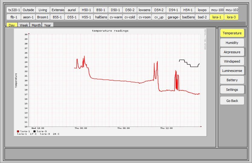
I added a DS18B20 (Dallas/OneWire) temperature sensor (Sketch on github). With MQTT I route the value of the sensor (and my other sensor which does temperature/humidity) to my home automation system (see 2 dials on the right)
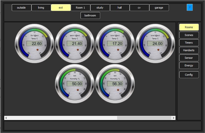
And in trend graph
Hey platenspeler, Nice work!
Could you tell me how to connect the RFM95 to the ESP. Which pins did you use and where are they defined?
Thanks!
René
René,
Please have a look at the documentation page: things4u.github.io
Look at the two pages documentiing the hardware setup.
Please let me know whether this is what you are looking for or information is still missing
Maarten
Thanks, will do!
Rene
Hi Maarten,
Trying to create a nice esp8266 node but keep getting “library lmic-v1.5 claims to run on [avr] architecture(s) and may be incompatible with your current board which runs on [esp8266] architecture(s)”. Did put your lmic library in arduino folder but still. Must be something stupid i do;)
error on esp:
wdt reset
load 0x4010f000, len 1264, room 16
tail 0
chksum 0x42
csum 0x42
~ld
Starting
hal_init: ESP architecture
FAILURE
C:\Program Files\Arduino\libraries\lmic-v1.5\src\lmic\radio.cpp:657
Ewoud