we try to use a RFM9x LORA radio with an ESP D1 mini .we have big problem with wiring the module . in the monitor we see that messages are normally send . but we don t have anything in the data console of ttn .
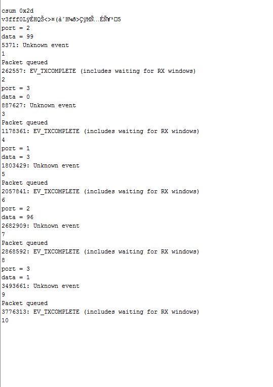
as you can see we have this in the monitor :
i think the problem is the " unknown event" that happened at each time .
for our pin mapping we do this ;
// Pin mapping
const lmic_pinmap lmic_pins = {
.nss = 15,
.rxtx = LMIC_UNUSED_PIN,
.rst = LMIC_UNUSED_PIN,
.dio = {4, 5, LMIC_UNUSED_PIN},
};
we do , but no sucess .
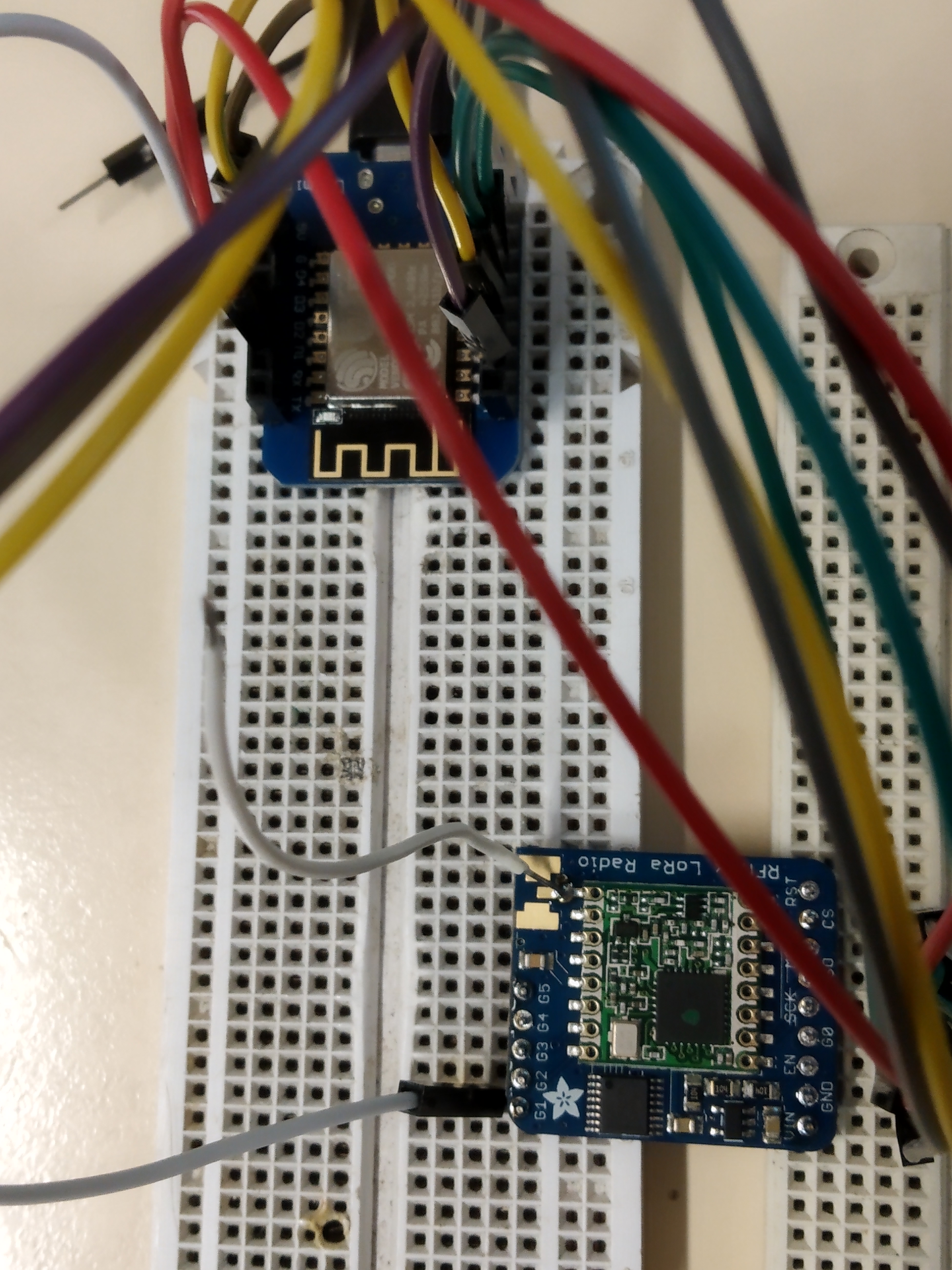
i think the wiring is different for our module because we don’t have just lora module but wa have something like this ;
do you tkink this type of module work same as the green card ?
what can be the unknown event ?
It is possble to connet mutiple devices to I2C. Just connect datapins to the CS line of the sensors and RFM. Trip that datapin when trying to read or write to that device.
I have 3 diodes from the 3 DIO-pins and a pull down to GPIO15 of the ESP12. Same pin-mapping as in:
May I use the next option in the Pin mapping to make it universal for LoRaWAN and FSK?
.dio = {15, 15, 15},
or
.dio = { 15, LMIC_UNUSED_PIN, LMIC_UNUSED_PIN},
The code compiles and and when I upload it to a Wemos D1 Pro, I get debug information in my Arduino IDE. When I connect the RFM95W I get nothing in my debug window. My questions:
I’m powering the unit from the USB port on my laptop. Will that work or does it require too much current?
I see various mentions of diodes, pull up resistors etc but I don’t use any and instead just use the wiring described on this page.
TTN is no longer able to support Single Channel Packet Forwarders - they are very non-compliant, devices expect to transmit on any one of 8 channels, they cause disruption to the network & other users and the owner. Please search the forum for more information.