Does anyone have any experience with using on board or hidden antennas? If I build an uber awesome cat tracking collar, I can’t see my cat walking around with a 6" antenna sticking up off it’s head.
Would love to know what you have tried and any suggestions you might have.
Yes you can find already those antennas main stream in catalogues like Farnell, Digikey.
Look for PCB patch antennas, PCB ceramic antennas. For 434/868/915 MHz.
If using these antennas, there isnt much art in design, just follow datasheet recommendations and propper PCB design.
But none of these on-board/flex antennas will beat a proper 1/4 wavelenght small wip. Use “guitar string” diameter wires and you will have great success.
Would you happen to know how much such a whip wire may be bent? Like when concealed in a collar, it won’t be straight at all. Wikipedia’s explanation on electrically short whips shows how a short whip could use a helix (see its photo). When using a “guitar string” wire, could one just fold it a bit…?
The most efficiency you would get of a typical 1/4wl antenna, is when it is perfectly perpendicular to its counterpoise/groundplane.
Having said this, any antenna can be bent to “infinite” (discarding that it may break) thus reducing its efficiency by changing its polar diagram and increasing SWR at the Radio side.
Helix antennas may be good for mobile operation but their efficiency is not as great as a perfect whip. Trade-offs always.
We have been using something called Nitinol Wire with great results in terms of RF and physical. It can be bent, tie knots, and other eccentricity uses and it will always return to its programmed state (ours is rectilinear/straight).
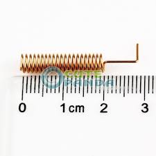
I just ran into a nice explanation of 433 MHz and 868 MHz Antenna Design Examples. It sounds good, but I don’t know if all details are correct. Also, I don’t know if the given coil diameter is for best reception, or is just a number that, combined with the number of turns, gets one the 1/4 wave length (8.6 cm for 868 MHz). (In the latter case, I guess I’d just mark that length before starting to wind the wire.)
For most applications, where space constraints exist, a simple Helical Antenna can be used. The Helical Antenna is a simple construction made from wound solid copper wire.
The groundplane stub between last turn and solder stub = 4.5 mm
Here is how to make such a helical antenna.
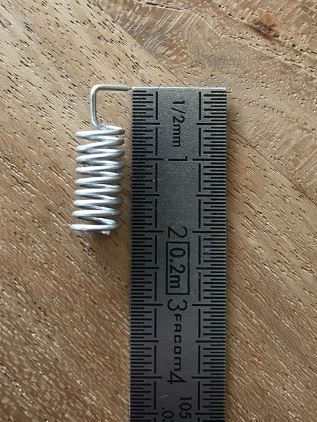
The material of the coil can be either solid copper wire or silver plated copper wire. The solid copper wire when pulled strongly gets a nice tension.
To pull the copper wire you start using about two meter of 1mm solid copper wire which is fixed to a sturdy anchor point. Take a piece of wood and wind the other end to the wood. Now start pulling with both hands on the wood side very slowly, until you notice the tension in the copper wire is getting loose - now pull it 30-40% in length with increased speed. This results in a very strong copper wire with a much higher tension, stiffness and perfect straightness with a diameter around 0.5 - 0.8mm.
Now take a rod like pencil or a drill with 5mm diameter and wind the wire around the rod as many time as mentioned above in the drawing according to the desired frequency.
Take care to create the groundplane stub on the lower end. It requires you to bend the wire in the axis away from the coil until it makes a small knee. Now add 3mm of wire by bending it 90 degree to the groundplane stub and the antenna is finished.
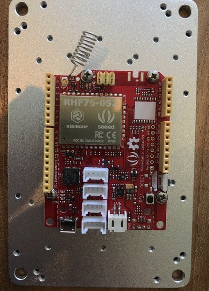
OK so here is my first attempt. Will have to do some range testing. I dont need tons of range maybe a couple of hundred meters through some forest. Anyone know if the last bend needs to be their or could I point it straight up vertical from the PCB ?

 )
)