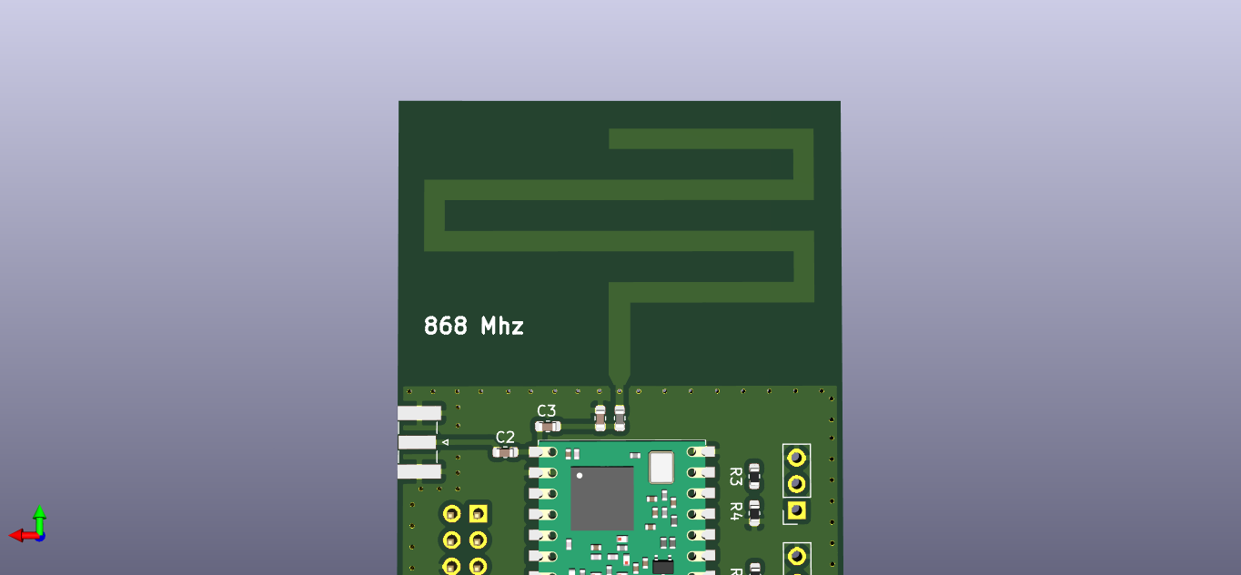
I am trying to design a PCB for a RFM95 and Arduino Pro Mini combination. I’d like to have both a PCB antenna and an optional SMA connection. I’ve designed the PCB antenna following DN024 guide. C2 and C3 are 100 pF caps and only one of them will be installed to select for the antenna to be used. I have a few questions regarding this design.
Firstly, there are tools to calculate trace widths for impedance control for 4 layer boards that has a reference plane. This is a two layer board with both sides filled with GND. Would copper fields effect the impedance? How can I calculate the trace widths in this case?
Second, PCB antenna design specifies a 1.8nH inductor to be used. I am having a hard time finding the part. How bad would it affect the matching if I used a value that is somewhat close to 1.8nH. For example JLC has a 1.2 nH inductor.
There are far more capable controller boards available these days where you won’t run into all kinds of limitations. Please consider using something else. For instance the STM blue pill but there are many other options as well.
And remembering this is the TTN forum, the use of a ProMini for a TTN node, is marginal, as has been suggested. The lack of Flash and RAM and probably speed too will limit the scope of applications the board is capable of.
Thank you! I’ll take your suggestions about the Pro Mini into consideration. For now, please humor me for educational purposes. RF design is very new to me and I’d like to learn.
No point having the best antenna design in the world if you can’t use a compliant stack. So please consider harder - use an ATmega4808 which will give you room to breath with the MCCI LMiC stack which is the only one likely to fair well with the v3 stack.
I could change the PCB to accommodate an STM32 Blue pill as suggested, without changing the placement of the antenna and the RFM95 module. My question, however, remains the same.