I am currently testing my first node using Arduino Mega and RN2483.
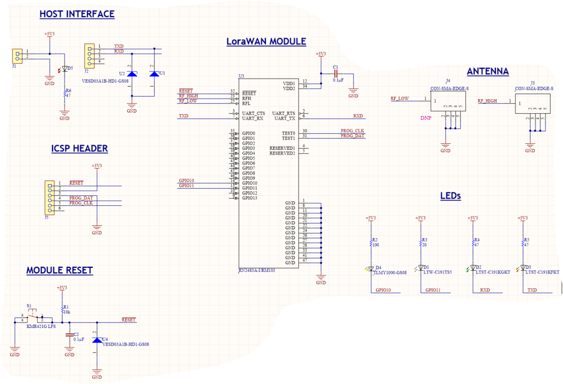
Facing Power-up issue: RN2483 module board is powered by 3.3V supply of Arduino Mega. After switching on, I measured voltage on TX, RX, GPIO10 & GPIO11 pins of RN2483. Following are the measured voltage values:
TX - 0.36V
RX - 0.88V
GPIO10 - 0.92V
GPIO11 - 1.72V
Are we supposed to get these values. I have attached the schematic for reference.
Even after initializing UART communication & sending character ‘X’ from Arduino, these values remain same. Reset doesn’t work on RN2483.
Has anyone else encountered this - and what could my actions be going forward?
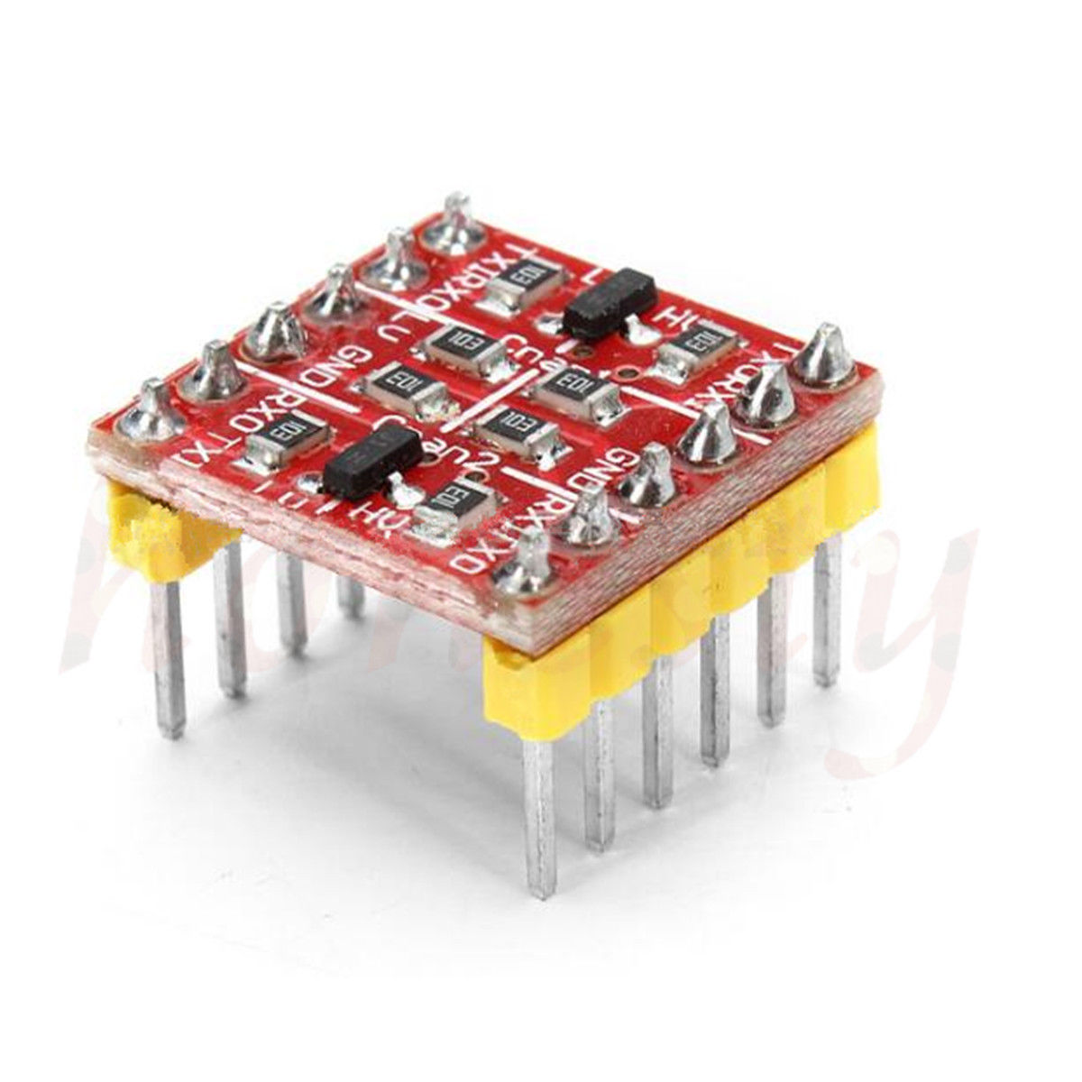
Yeah. I am using a shield on Arduino Mega with leve) converter. TX line from level converter to RN2483 is working fine (measured 3.24V, sending character ‘X’). Issue arises when I connect and power-up RN2483 module, TX line from level converter drops down to 0.88V.
Removed ESD protection diode and tested again, working fine now; wrongly selected 3.3V reverse stand-off ESD. Whenever UART lines were exceeding 3.3V (due to some noise in the line), ESD diode was clamping them to GND.