There are two specific versions of the RAK831 board… One set for working around 866Mhz, and one set to work around 915MHz. So first up, you need the right RAK831 board for your location.
Once you have the right board for your location, you ALSO need to make sure you get the right global config file in place for your specific location. because the basic project we are making use of here (actually developed to work with ic880a board) seems to be just expected to work in EU… as ic880a is only available in EU frequency range.
The AU and the HK (and US, and others) global config files all require you to be using the “915” version of the RAK831 board, but then the specific region config file specifically sets the operating channels around 915MHz to suit the different region requirements.
I have 2 here and one has a sticker with 868 on it, the other one has no indentfication.
Without test equipment it will be difficult I think… did you contact RAK… they are very helpfull.
The serial number is on one of the two strips on the sides of the PCB. This was an incorrect assumption.
The number on one of the strips is not the serial number but probably a PCB model/version identifier. These strips are usually removed after the PCB production process. I’m not sure why RAK leaves them on.
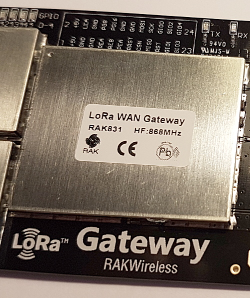
Like @BoRRoZ mentioned the RAK831 should have a label like below where the frequency band is explicitly specified. But there are boards without the label. Older versions may not have it.
On the RAK831 packaging I could find the following identifiers:
On the first label:
RAK PART NO: RAK831(868MHz)
So here the frequency band is also specified.
Date Code: yyww
Production week, where yy is the year in 2 digits and ww is the week number.
LOT Number: GSZxxxxxxxxxxx
Where the x’s are an 11-digit number. It is also represented with a BAR Code. This appears to be a product code similar to an EAN code (but might also be a batch number).
On the second label:
Modle NO: RAK831 Probably a typo and here no frequency specification.
Series number: yyyymmddxxx
Where the first part is the date and xxx is a 3-digit (sequence) number.
This could possibly be a unique serial number (although less likely because it does not include some product ID) but it could also be some kind of batch number (due to ‘Series’, but that may also be a typo for ‘Serial’).
Except for ‘RAK831’ and the frequency band on the label, none of the other information is listed on the board.
So you should be able to find the frequency band on the label on the board (or on the original packaging).
If the label and packaging are missing then there are no visual clues.
gosh… so much hassle. If the supplier can’t get you up and running, then I’d be returning it as not working to the suppler, and ordering straight from RAK.
And if I couldn’t return it to supplier, then I’d be taking the financial cost as a lesson to not waste time with bad suppliers in future…
I had a colleague to visit their office the other day and they replaced my RAK831/RAK811 from 868Mhz to 915Mhz versions so I can use AS923 band. Perhaps they are not the best with communications but they aren’t bad.
Anyone has experience with needing to reset the RAK831 board or the concentrator will not start?
I have to run below code everytime I restart my RAK831 or the gateway will not work with this error as shown in /var/log/syslog
There should be a start script at /opt/ttn-gateway/bin/start.sh
At the beginning of this script you will find some lines to generate a reset on pin 25. Change the pin number from “25” to “17”.
More info on RAK831 installation and configuration here.
Works well thanks. But I wonder why one will have to change the reset pin? Is it because the or original software is based on ic800a which has a different pin mapping?
It’s just a matter of the wiring between the RAK831 and the Raspberry/Orange Pi that is used to control the RAK. The reset pin on the RAK is 19, which can be wired to any output pin of the Pi. The standard Pi pin for this is 25, but it looks like you are using pin 17. In my set-up I’m using pin 10 of the Pi because the Orange Pi does not have pin 25.
For info
Just got the RAK831 running with a R.Pi 3 B+ using these instructions https://www.thethingsnetwork.org/labs/story/rak831-lora-gateway-from-package-to-online
All was OK, but because I’m using the RAK831 adapter board (it has a GPS), I had to change the “start.sh” script.
I changed this line (near the beginning)
from
SX1301_RESET_BCM_PIN = 25
to
SX1301_RESET_BCM_PIN = 17
This was done using the R.Pi command
sudo nano /opt/ttn-gateway/bin/start.sh
Once you’ve made the change, press “Cntrl and O” to write out the file change and exit using “Cntrl and X” (need to reboot of course)
I’ve got a few of Charles’ boards to try - so I hope to try that soon.
Reason for the post was to record more specific help e.g. how to edit the file and what board was being used at the time.
Thanks for the link - I can see that it is more geared to a R.Pi Zero using the board from Charles (I’ll try to use it next with the board from Charles) - but why is it better for a R,Pi 3B?
Lora Gateway base setup for SX1301 based concentrators
This setup is used for some LoraWAN concentrators based on small computers such as Raspberry PI or others. For example it works fine with the RAK831 PI Zero shield
.
Because it provides a better and more secure implementation of the gateway software: @kersing’s Multi Protocol (MP) Packet Forwarder.
mp-pkt-fwd uses the new protocolbuffers-over-mqtt-over-tcp protocol for gateways, as defined by TTN and used by the TTN kickstarter gateway. Using this protcol the gateway is authenticated, which means it is registered under a specific user and can thus be trusted. Because it uses TCP, the chance of packet loss is much lower than with the previous protocol that used UDP. Protocolbuffers packs the data in a compact binary mode into packets, using much less space than the plaintext json that was previously used. It should therefore consume less bandwidth.
Questions will be asked during setup (but this may not become directly clear from reading readme.md).
For your RAK831 Raspberry adapter board just skip the LED, (switch) monitoring and OLED display stuff when asked during setup.
@Charles added extra features to the setup procedure since I used it. Like questions to skip certain parts of the installation (relevant for specific boards/options only) so the setup can be used for more adapter boards. And there is now support for an OLED display.
(FYI @kersing’s MP Packet Forwarder repository contains the gateway software but not an installer.)