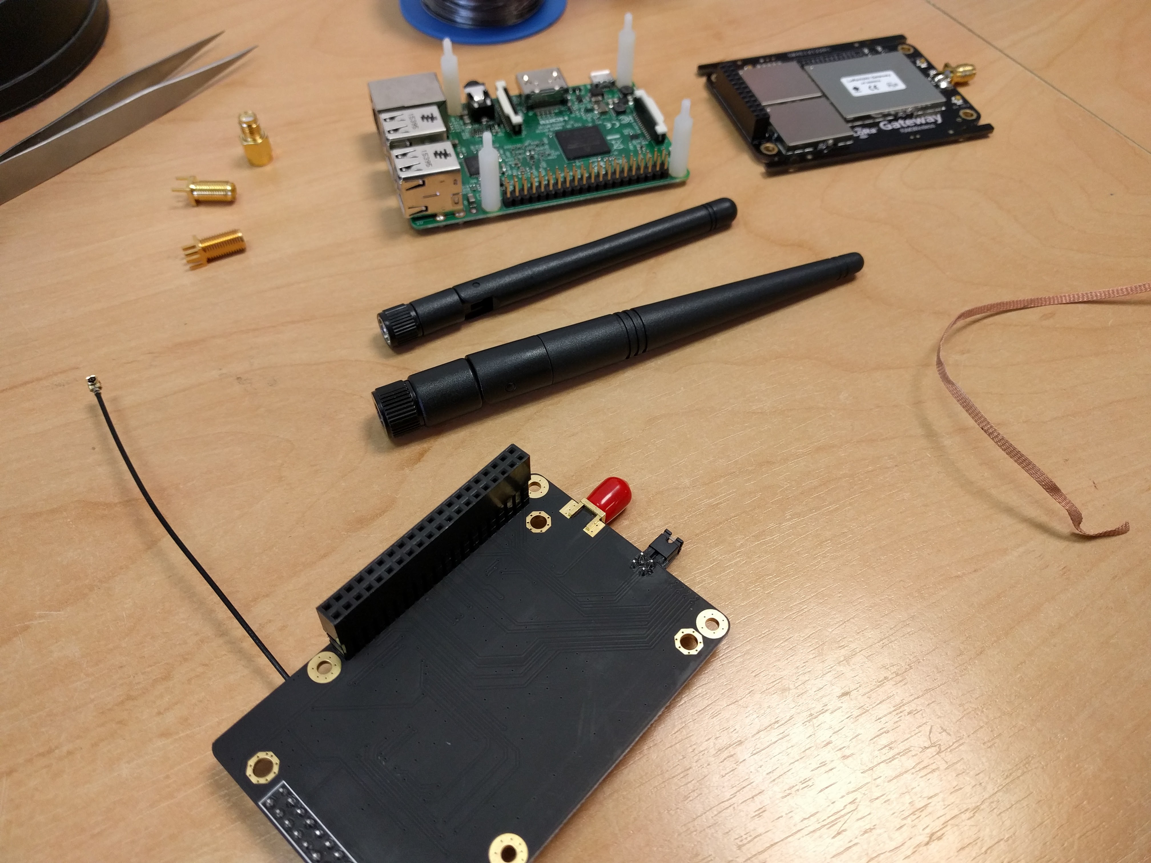
About a month ago I ordered the RAK831 and its Pi converter board. I plan on using it as a mobile Gateway so I wanted to place the GPS module as well. After checking the differences between the MAX-7 from U-Blox and the L70 from Quectel I found that they have compatible footprints and functionality. The L70 is extremely good to source here in the NL trough RS Online ( 908-4091, L70B-M39, 12 euro’ s ) and cheap as well.
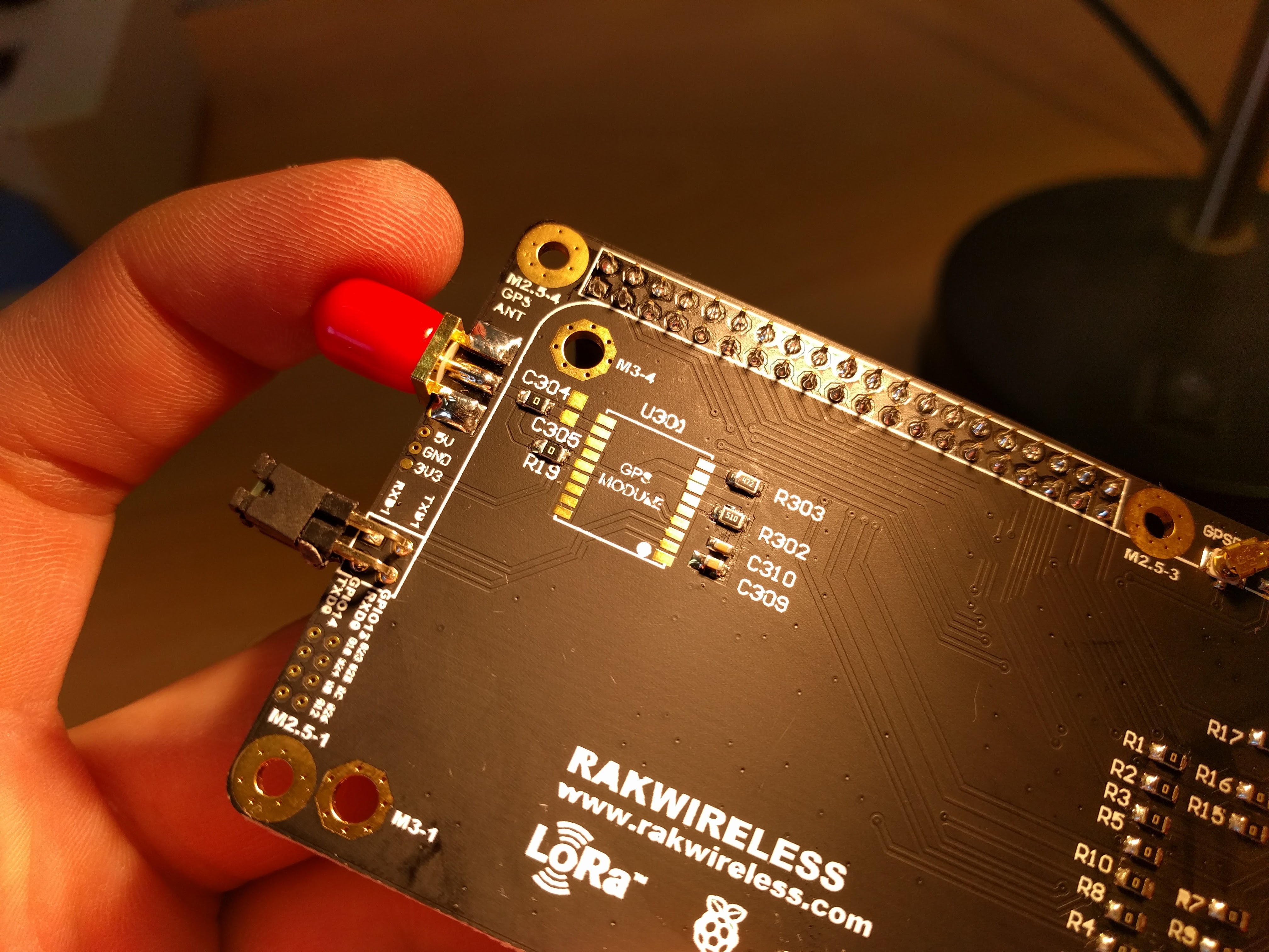
Once arrived I was a bit surprised by the GPS board:
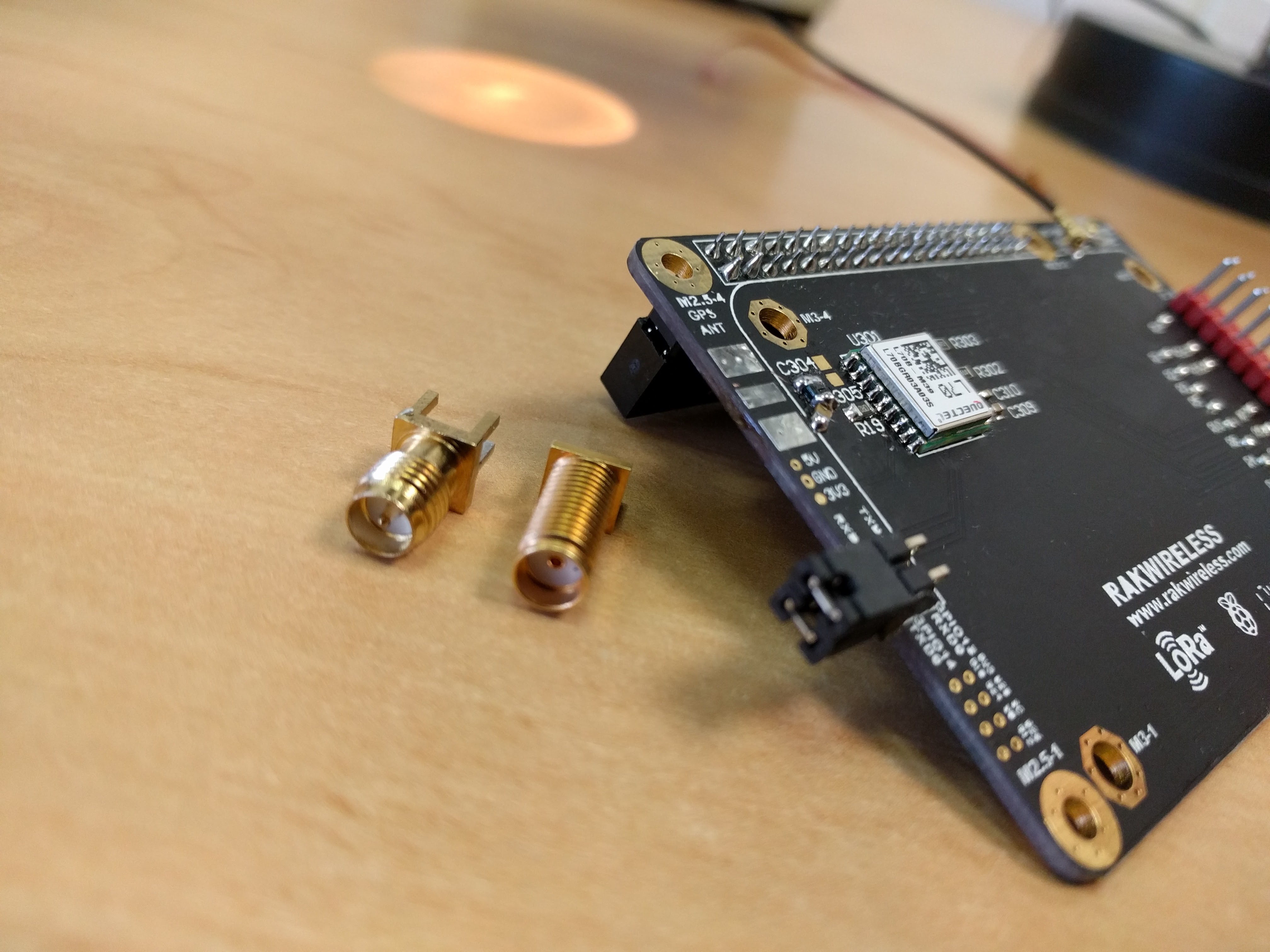
Normally you connect an active antenna to this kind of GPS receiver. The power for this antenna is sourced over the coax cable from the receiver to the antenna. Normally this power is injected trough an inductor that serves as a low impedance for DC and a high impedance for the GPS 1.5Ghz signals, surprisingly on this board they don’t use an inductor by seem to rely on the pcb trace inductance. Even more surprising they connect the 3V3 from the Pi directly to the VCC and VCC_RF! The VCC_RF is an output (to supply power to the antenna) and no power input. The VCC_RF is probably filtered internally to reject some of the regular power supply noise.
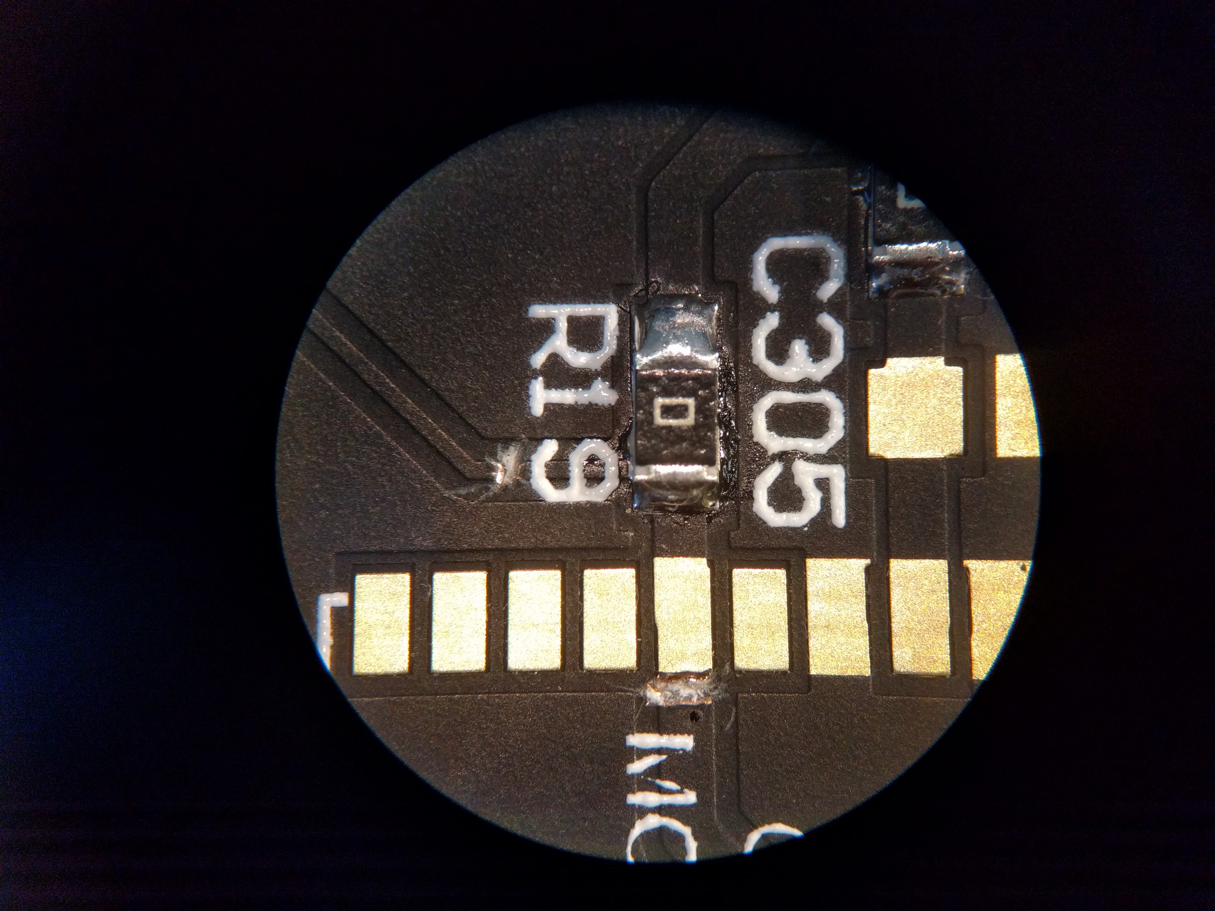
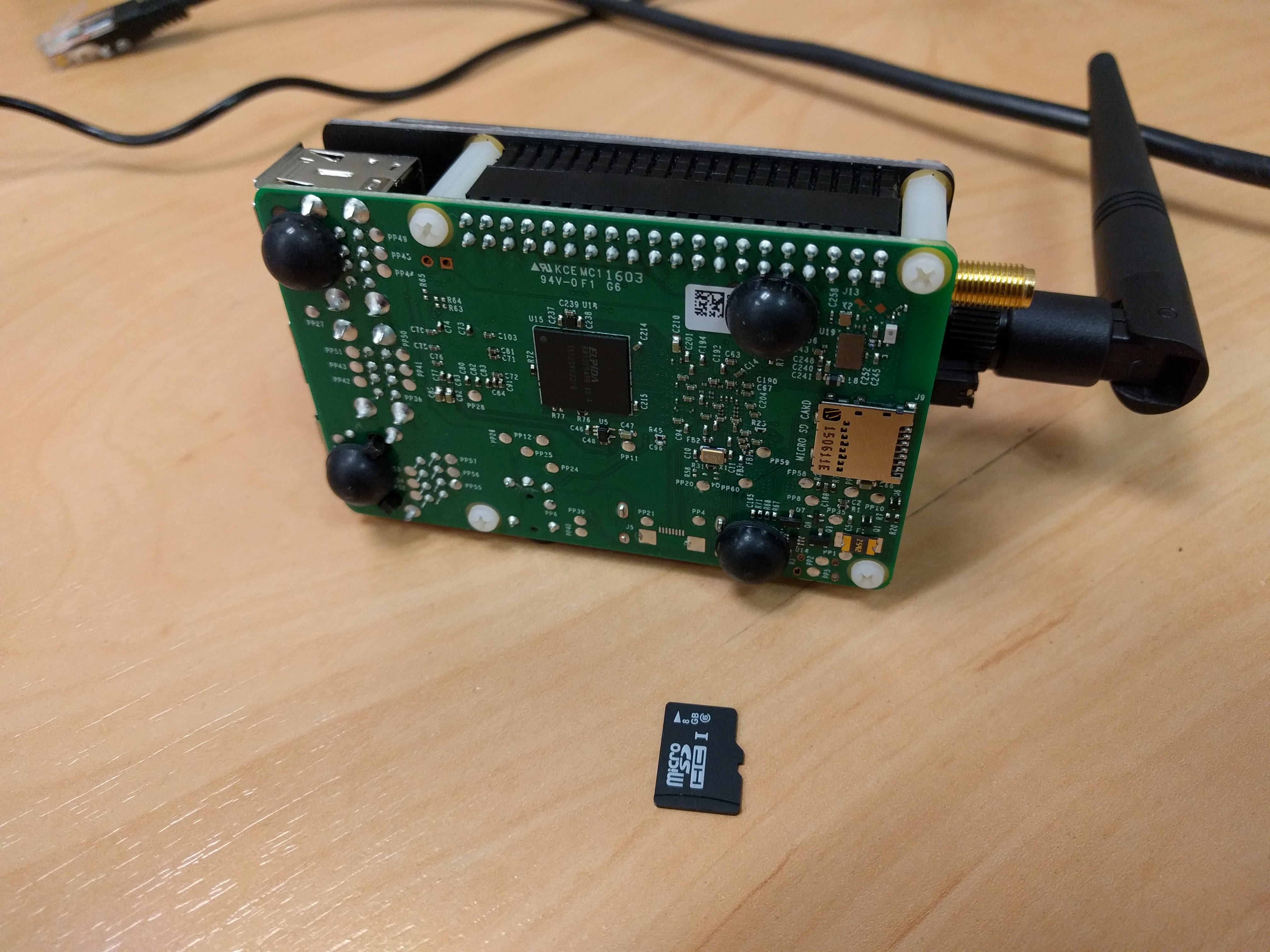
I felt a bit bad for the module so I modified the board to match the datasheets recommended power injection circuit. I cut the 3V3 traces:
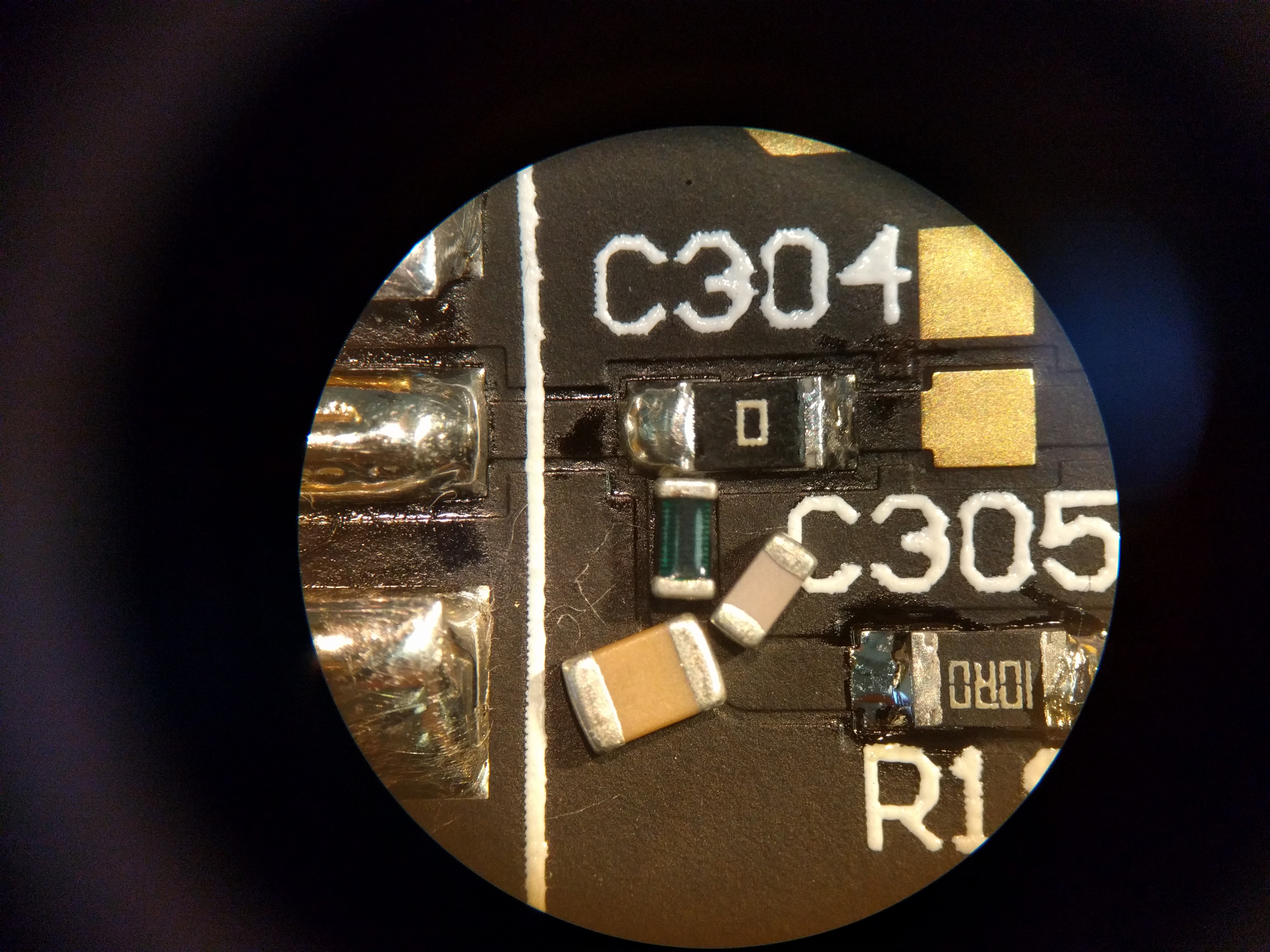
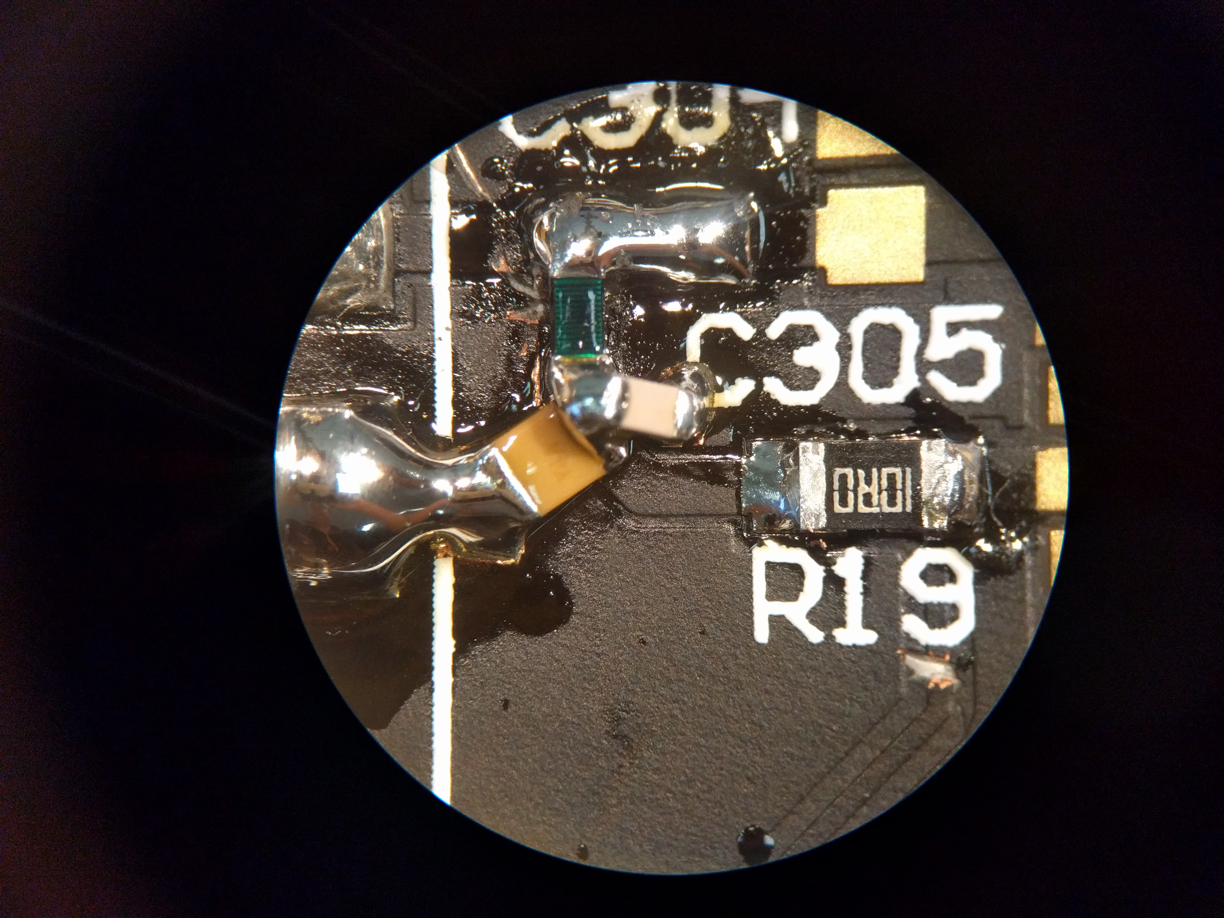
And replaced R19’s 0R by 10R as recommended by the datasheet. Luckily I had all components around and placed them on the board to determine their location:
The result (I also removed the other 0R resistor and replaced it by a blob of solder):
They also seemed to have cut corners on soldering the SMA connector:
They completely neglected to solder the SMA-RP connector on the bottom side on both the GPS port and the RAK board. I was actually quite happy since this made removing the horrible reversed polarity connectors way easier:
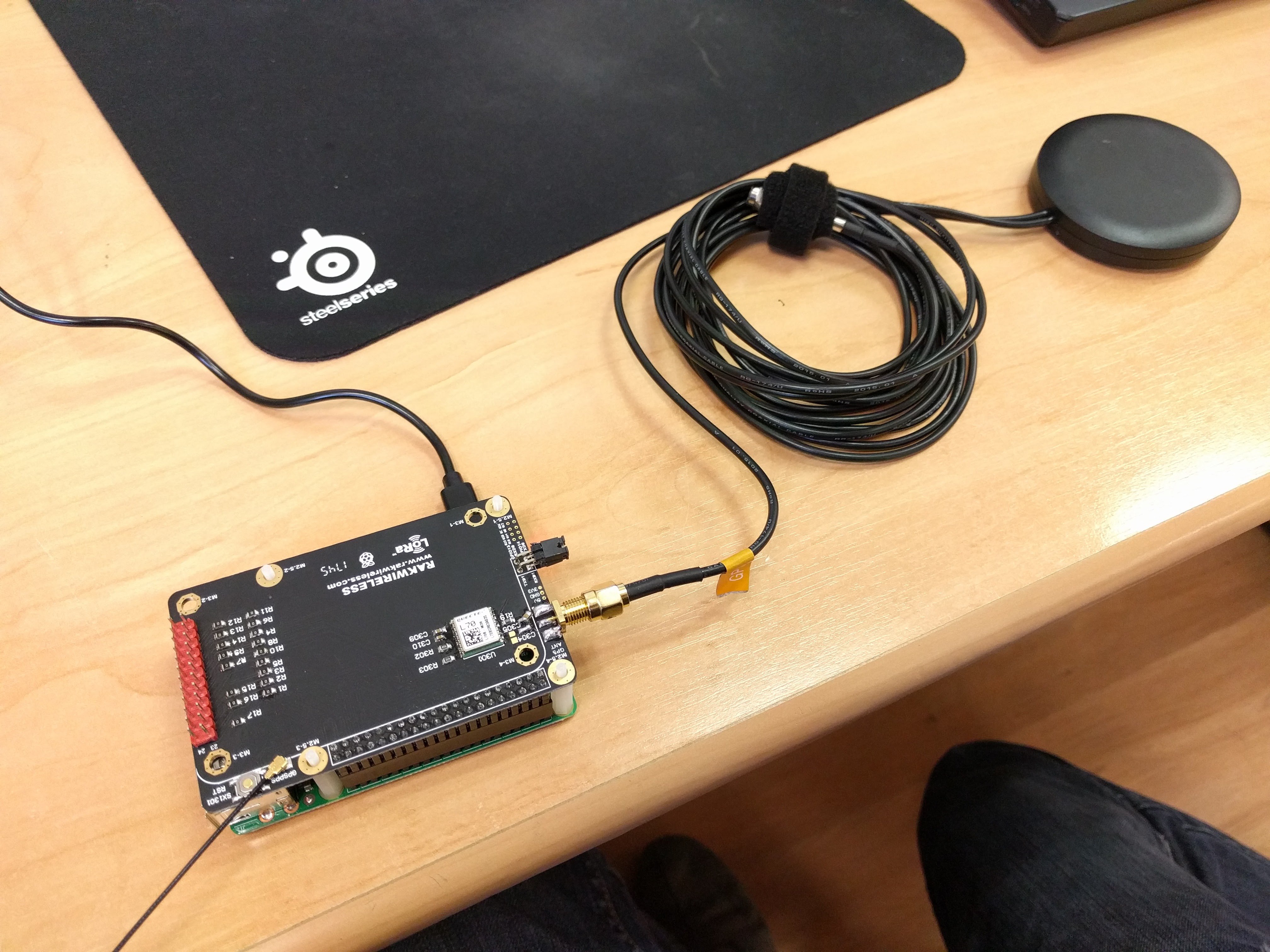
I swapped the SMA-RP for SMA connectors on both boards:
And tested the GPS receiver:
Works!
This allowed me to use the FLEXI-SMA90-868 I from RS without an SMA-RP - SMA adapter. Finally I added some rubber feet and now everything is operational!:
This made me wonder, is there anyone who got the GPS working with the stock board?
True, unfortunately no binary protocol. I am using mp_pkt_fwd and it seems to support both NMEA and UBX (as far as I experienced it works and the source has code to process it as well), so I am happy ^^.
Another option for using the RAK RPi Converter Board with an Active GPS Antenna: MAX-7W
Instead of using a U-Blox MAX-7Q module or a Quectel L70 module and having to add (hack) three additional components onto the board for using it with an active GPS antenna, another option is using a U-Blox MAX-7W module instead.
The MAX-7W module already has the required additional components for an active antenna.
Only one component will have to be added for the MAX-7W: a 10 ohm resistor (‘Rbias’) between V_ANT (pin 15) and VCC_RF (pin 14). This will also require a manual hack, but much simpler to add and will be less error prone.
As delivered RAK’s RPi Converter Board (the GPS part) seems incorrectly wired, neither suitable/optimal for passive GPS antenna nor for active GPS antenna.
Below the issues:
GPS module VCC_RF (pin 14) is hard-wired to 3.3V but it should not.
Hard-wired via a PCB trace below the GPS module from pin 14 to pins 7+8.
For compliance with the U-Blox documentation this trace should be cut as described by @JTAG above (be careful for the via next to pin 13’s soldering pad).
Another trace goes from VCC_RF to the 3.3V pad marked ‘3.3V’ on the outer side on the board. This trace should also be cut to prevent possible future issues because it is not a 3.3V pad but the GPS module pin 14.
Antenna / GPS module RF_IN (pin 11) is wired directly to 3.3V via 0 ohm resistor R19 but it should not.
For compliance with the U-Blox documentation R19 should be removed.
According to U-Blox documentation, without required additional components (coil, capacitor and resistor) the U-Blox MAX-7Q will not (properly) support an active GPS antenna.
These components are missing on the converter board and there are no free soldering pads for adding them manually later.
For using the board with an active GPS antenna there are two options:
Use a U-Blox MAX-7Q or Quectel L70 module, apply the above two fixes and add the required additional components as described by JTAG (note: L70 lacks U-Blox’ binary UBX protocol), or
Use a U-Blox MAX-7W module (already has components required for active antenna), apply the above two fixes and connect a 10 ohm (Rbias) resistor between V_ANT (pin 15) and VCC_RF (pin 14). (Also includes antenna shortcut protection.)
Optional:
If not implementing JTAG’s modifications (adding the three components, which uses this trace) cutting the following PCB trace will prevent it from having possible negative impact on the antenna signal:
Cut the PCB trace from R19 to the unlabeled 0 ohm resistor that is connected to RF_IN. Cleanly and directly below the unlabeled 0 ohm resistor. The trace is then not connected to RF_IN anymore.
Hi… I got the GPS working fine with the stock board.
I can read the coordinates well on the RPi.
I just read this and realize the issue, and found my board have it.
What is the impact if I didn’t do the HW modification? any longterm effect? Please advice.
Thanks
Following the documentation is very recommended since this is tested by the manufacturer.
Theoretically, connecting RF_IN pin to 3.3v should not cause you problem since it has dc blocking internally but noisy supply lines might affect your rf signal. Not very good on rf electronics.
Found that there are some other annoying things, like the I2C pins are misused for something else, had to use
dtoverlay=i2c-gpio,bus=3,i2c_gpio_sda=23,i2c_gpio_scl=24
for assigning new pins. Now I can connect a BME280 to go with it in the outdoor box and report the box conditions.
Apologies for bumping an aged thread. Were you able to mount a BME280 to the RAK convertor board directly? Or did you do any physical modifications to enable this?
Using NMEA “RMC” messages instead of UBX “NAV-TIMEGPS” can, in conjunction with pps signal, result to lock the pps signal of libloragw on the next second. The gateway then shows a wrong (+1 sec) time.