RFM95 testing

Hi,
I’m having a problem. I got a new RFM95 module and I’m using the Arduino LMIC library. I soldered it to my PCB and tested it. I got an error in the command line in the radio.c file at the line 689 where the assigning of the SPI adress happens. That means a hardware/connection problem. When desoldering, I slightly damaged the board. I accidentally removed this component:
rfm95

I don’t know whether its a crucial part or not. But later when I connected the module to an Arduino UNO, I got a response on the command line saying “EV_TXCOMPLETE (includes waiting for RX windows)”. This should mean that the module is fine, right? I don’t see no data on the TTN console, though.

Any ideas? Should I get a new module or is this fine? Do you know the name and value of the part so I could replace it?

If the module is working maybe there is a problem with my connection. Is this schematic correct?
architecture

I could really use your help right now. Thanks.

maybe place your complete (formatted) code here too just to see if everything is right ?

  • haven’t find out yet what that component does that you removed :sunglasses:
    rfm96

Yeah sure I’m just using the ttn-abp example sketch with changed keys and pin maping.

My code:

#include <lmic.h>
#include <hal/hal.h>
#include <SPI.h>
static const PROGMEM u1_t NWKSKEY[16] = { 0x40, 0xD4, 0xC1, 0xBE, 0x01, 0x37, 0xB2, 0x33, 0xF0, 0xCC, 0xF1, 0xAF, 0xB2, 0xEA, 0x09, 0x26 };
static const u1_t PROGMEM APPSKEY[16] = { 0xCD, 0xA6, 0xA4, 0xD9, 0x62, 0x16, 0x67, 0xAE, 0xB0, 0x66, 0x1B, 0xED, 0x71, 0x12, 0xB9, 0x9D };
static const u4_t DEVADDR = 0x26011C97;
void os_getArtEui (u1_t* buf) { }
void os_getDevEui (u1_t* buf) { }
void os_getDevKey (u1_t* buf) { }
static uint8_t mydata = “Hello, world!”;
static osjob_t sendjob;
const unsigned TX_INTERVAL = 20;
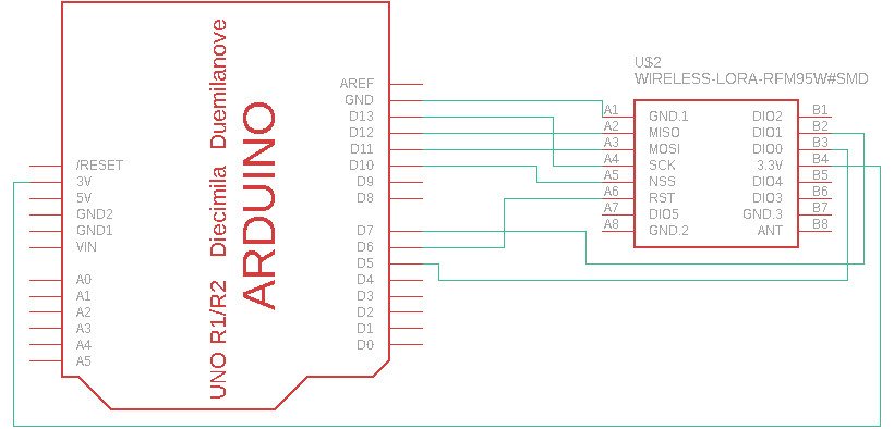
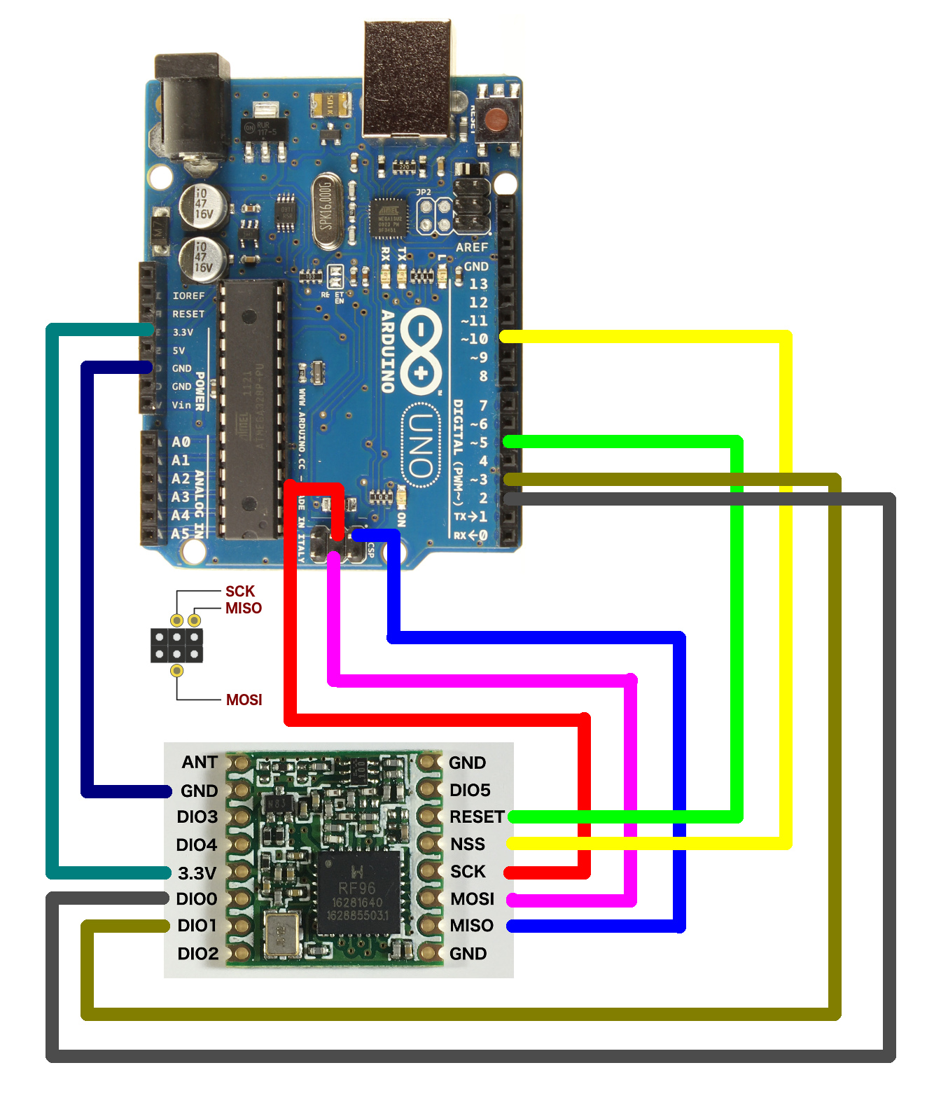
const lmic_pinmap lmic_pins = {
.nss = 10,
.rxtx = LMIC_UNUSED_PIN,
.rst = 5,
.dio = {2, 3, LMIC_UNUSED_PIN},
};
void onEvent (ev_t ev) {
Serial.print(os_getTime());
Serial.print(": ");
switch(ev) {
case EV_SCAN_TIMEOUT:
Serial.println(F(“EV_SCAN_TIMEOUT”));
break;
case EV_BEACON_FOUND:
Serial.println(F(“EV_BEACON_FOUND”));
break;
case EV_BEACON_MISSED:
Serial.println(F(“EV_BEACON_MISSED”));
break;
case EV_BEACON_TRACKED:
Serial.println(F(“EV_BEACON_TRACKED”));
break;
case EV_JOINING:
Serial.println(F(“EV_JOINING”));
break;
case EV_JOINED:
Serial.println(F(“EV_JOINED”));
break;
case EV_RFU1:
Serial.println(F(“EV_RFU1”));
break;
case EV_JOIN_FAILED:
Serial.println(F(“EV_JOIN_FAILED”));
break;
case EV_REJOIN_FAILED:
Serial.println(F(“EV_REJOIN_FAILED”));
break;
case EV_TXCOMPLETE:
Serial.println(F(“EV_TXCOMPLETE (includes waiting for RX windows)”));
if (LMIC.txrxFlags & TXRX_ACK)
Serial.println(F(“Received ack”));
if (LMIC.dataLen) {
Serial.println(F(“Received “));
Serial.println(LMIC.dataLen);
Serial.println(F(” bytes of payload”));
}
// Schedule next transmission
os_setTimedCallback(&sendjob, os_getTime()+sec2osticks(TX_INTERVAL), do_send);
break;
case EV_LOST_TSYNC:
Serial.println(F(“EV_LOST_TSYNC”));
break;
case EV_RESET:
Serial.println(F(“EV_RESET”));
break;
case EV_RXCOMPLETE:
// data received in ping slot
Serial.println(F(“EV_RXCOMPLETE”));
break;
case EV_LINK_DEAD:
Serial.println(F(“EV_LINK_DEAD”));
break;
case EV_LINK_ALIVE:
Serial.println(F(“EV_LINK_ALIVE”));
break;
default:
Serial.println(F(“Unknown event”));
break;
}
}
void do_send(osjob_t* j){
// Check if there is not a current TX/RX job running
if (LMIC.opmode & OP_TXRXPEND) {
Serial.println(F(“OP_TXRXPEND, not sending”));
} else {
// Prepare upstream data transmission at the next possible time.
LMIC_setTxData2(1, mydata, sizeof(mydata)-1, 0);
Serial.println(F(“Packet queued”));
}
// Next TX is scheduled after TX_COMPLETE event.
}
void setup() {
Serial.begin(9600);
os_init();
LMIC_reset();
#ifdef PROGMEM
uint8_t appskey[sizeof(APPSKEY)];
uint8_t nwkskey[sizeof(NWKSKEY)];
memcpy_P(appskey, APPSKEY, sizeof(APPSKEY));
memcpy_P(nwkskey, NWKSKEY, sizeof(NWKSKEY));
LMIC_setSession (0x1, DEVADDR, nwkskey, appskey);
#else
LMIC_setSession (0x1, DEVADDR, NWKSKEY, APPSKEY);
#endif
LMIC_setupChannel(0, 868100000, DR_RANGE_MAP(DR_SF12, DR_SF7), BAND_CENTI); // g-band
LMIC_setupChannel(1, 868300000, DR_RANGE_MAP(DR_SF12, DR_SF7B), BAND_CENTI); // g-band
LMIC_setupChannel(2, 868500000, DR_RANGE_MAP(DR_SF12, DR_SF7), BAND_CENTI); // g-band
LMIC_setupChannel(3, 867100000, DR_RANGE_MAP(DR_SF12, DR_SF7), BAND_CENTI); // g-band
LMIC_setupChannel(4, 867300000, DR_RANGE_MAP(DR_SF12, DR_SF7), BAND_CENTI); // g-band
LMIC_setupChannel(5, 867500000, DR_RANGE_MAP(DR_SF12, DR_SF7), BAND_CENTI); // g-band
LMIC_setupChannel(6, 867700000, DR_RANGE_MAP(DR_SF12, DR_SF7), BAND_CENTI); // g-band
LMIC_setupChannel(7, 867900000, DR_RANGE_MAP(DR_SF12, DR_SF7), BAND_CENTI); // g-band
LMIC_setupChannel(8, 868800000, DR_RANGE_MAP(DR_FSK, DR_FSK), BAND_MILLI); // g2-band
LMIC_setLinkCheckMode(0);
LMIC_setDrTxpow(DR_SF10,14);
do_send(&sendjob);
}
void loop() {
os_runloop_once();
}

in your schematic I see an I2C device that I don’t see in your code ?

For first that’s not my schematic its a schematic a I found online and I was inspired by it. I think it looks way clearer than mine and the connection with the module is the same that’s why is used it.

This is my actual schematic:
schematic

The second reason why there isn’t the I2C device yet is that I want to keep the code simple so I know that there are problems with the radio not with the sensor.

  • recapitulate… (I’m slow) So you have a possible broken RFM95 module, that was first connected to a 328 pro mini and now its connected to a arduino uno and gives “EV_TXCOMPLETE (includes waiting for RX windows)” with the same code
  • the module never worked before as far as you know.

Yeah sorry I’m just very stressed because it’s a new module and I’m running on a tight deadline so I need to get it working.

You got that right. I had it connected to my own PCB which is basically a pro mini copy with some extra components. Here is a picture:complete

But it didn’t work at all so I removed the module. Now I have it connected to a UNO with jumpers.

I got the module today so it didn’t work before.

Also maybe it’s worth mentioning that I worked with Adafruit Feather which includes RFM95 before and I remember that it took me about 2 weeks to get it working at all and I know people that have bad experience as well.

one thing I am thinking of is

The max voltage level for the RFM95 is 3.7 volt.
That works fine with an 328 at 3v3… but you’ve connected it to the UNO … possible without level shifter

+1

Not good.

Easy to check.

Change the pin number in the code that is the NSS select line for the RFM95, with the program now unable to access the RFM95, what happens ?

It’s possible but there are many tutorials using UNO with RFM95 so it should work. I can test with an actual pro mini or with ESP32.

I get this on the command line:

08:34:55.597 → FAILURE
08:34:55.597 → C:\Users\U⸮⸮vate⸮\Documents\Arduino\libraries\arduino-lmic-master\src\lmic\radio.c:689

I get the same when I disconnect the RFM95 from power.

Without level converter it should not. Manufacturer states the device is 3v3 so it should be used with 3v3 i/o only.

Okay so I successfuly got a ping from UNO. I just needed to add a jumper from the RESET pin and change the pin mapping.

Will let you know whether it will work with the pro mini (with my PCB).

For the benefit of others who may search these forums for the same problem, could you provide more details of what the problem was ?

Ugh it’s not working again. Firstly I got error at line 689. Line 689 looks like this:

ASSERT(v == 0x12 );

Then I removed the connection with DIO2 and also disconnected the jumper from DIO5 and connected it to RST. My schematic looks like this now:
schematic

It did work really well I received uplink more than 20 times. Now I just get error at line 545. This is line 545:

ASSERT((readReg(RegOpMode) & OPMODE_LORA) != 0);

Maybe there is just a sold solder joint or something I’ll need to resolder it. It’s very strange because it worked before.

my guess… you just killed it :wink:

1 Like

You have just connected a 5V Arduino with 5V logic outputs to a 3.3V RFM95.

RIP RFM95 I guess.

1 Like

After throghout examintation, I must conclude that RIP RFM95 indeed. I get a message like this:

20:26:36.654 → 395373: EV_TXCOMPLETE (includes waiting for RX windows)
20:26:36.688 → FAILURE
20:26:36.721 → C:\Users\U⸮⸮vate⸮\Documents\Arduino\libraries\arduino-lmic-master\src\lmic\lmic.c:1889

Firstly its saying that the transmittion has been completed successfuly but then its shows an error. It’s sad because there are many schematics on the internet, which look like this:


But it’s mostly weird because the module functioned perfectly for over an hour and then broke.

The replacement will arrive in about a week, will report here. Until then, what are the precautions I need to make? Can I use it with UNO and a level shifter? And can I use it normally with ESP32? Thanks.

Yes, there unfortunately are a lot of people out there posting rubbish tutorials on how to connect stuff. Problem is these ‘tutorials’ look so convincing.

I note that with that tutorial several posters reporting problems and commented on the inappropriate connection of a 3.3V RFM95 to a 5V Arduino. You might have expected the tutorial to be corrected.

Its not weird at all your module appeared to initially work, its being operated well outside the ratings specified in the datsheets, who knows exactly what is going to happen.

In addition some UNOs are limited to 50mA on thier 3.3V supply output which is not really enough for an operating RFM95, that rarely gets mentioned either.

Might be an idea to remove the graphic you posted, someone glancing at the post might think its how you actually should wire an RFM95.